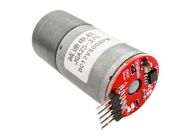
Our JGA25-370 Onboard Motor Driver is an easy to use motor driver board that attaches to the back of almost any JGA25-370 motor/gearmotor. It works for any motors that run at 4.5V to 48V, and has a max current rating of 3.7A. Just solder the output terminals to your motor and you are ready to go!
Layout
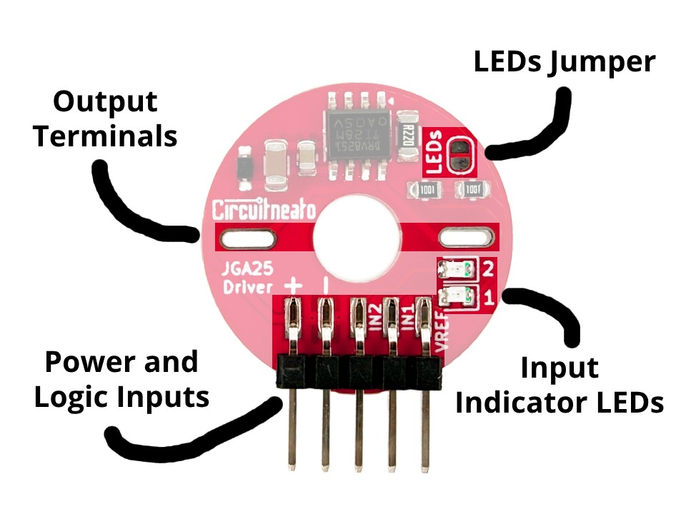
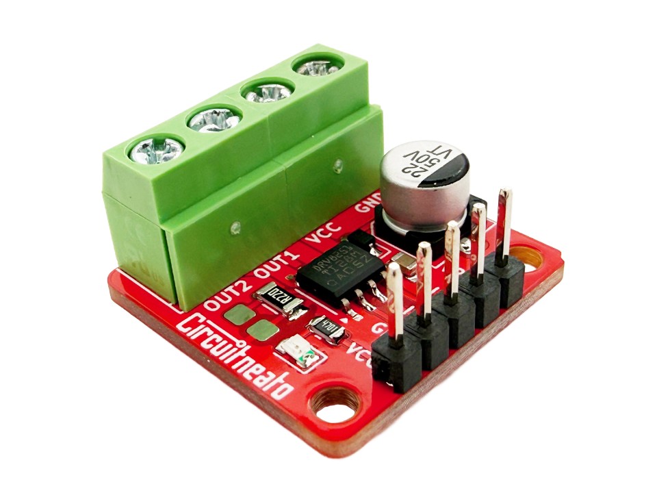
The motor driver has two output terminals which solder to the motor terminals on the back of most JGA25-370 style motors. The diameter of a usable motor should be 24mm and the terminals be under 20mm apart at the furthest distance, and over 13mm apart at the shortest distance. Those output terminals can also be soldered to wires which can be connected to any brushed DC motor that is within the driver’s ratings. There are 5 male headers sticking out the side of the board, which connect to power, ground, input 2, input 1, and VREF. There is also an indicator LED for input 1 and another indicator LED for input 2. As well as an “LEDs” jumper that can be cut to disable those LEDs.
Features
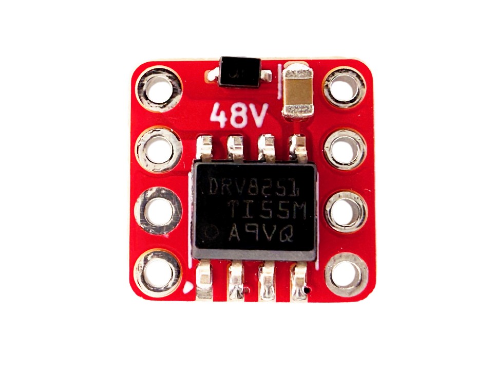
The motor driver chip on this board is the DRV8251, which is an H-Bridge brushed DC motor driver. It can support 1.8V, 3.3V, and 5V logic levels, and has a supply voltage range of 4.5V – 48V. It has a peak current of 3.7A, and a continuous current of about 2.3A. More features include:
- PWM control
- 450mΩ RDS(on)
- Overcurrent protection
- Thermal shutdown
- Undervoltage lockout
Usage
This motor driver is easy to control with any microcontroller board like an Arduino UNO, or our Tineato 3226. Start by soldering the output terminals to the terminals on your motor. The driver board should be pushed all the way onto the back of the motor, then soldered on from the top. You can also use wires to connect the output terminals to different sizes of motors (24AWG to 20AWG work fine).
Then connect 4.5V-48V to the + pin, connect GND to the – pin, and connect two control inputs to IN1 and IN2. You can use PWM signals on both IN1 and IN2 for motor speed control. Note that whatever motor terminal is connected to which output terminal does not matter, it will only change the direction of the motor if flipped. Also make sure there is a common ground between the microcontroller board and the driver.
Your logic voltage supply should also be connected to the VREF pin to enable the current limit. At 5V, the current limit will be ~2.3A, and at 3.3V the current limit will be ~1.5A. You can calculate the current limit by dividing the voltage by 2.2. If you don’t want a current limit, then use a wire and/or solder to bridge across the “R220” shunt resistor. If this is done you will still need to provide your logic voltage on the VREF pin.
A high signal on IN1 (1.5V – 5.5V) and a low signal on IN2 (0V) will make the motor spin one way, and the opposite will make the motor spin the other way. PWM signals on the inputs will change how fast the motor spins.
Below is an example using our Tineato 3226 development board. Remember that any development board/microcontroller board can be used. First we will connect the GND and VCC pins from our power supply to the - and + pins on our driver respectively. We will also make sure to connect the GND pin from our Tineato 3226 to the power supply GND. Then connect pin 0 on our Tineato 3226 to IN1, pin 1 to IN2, and the VCC pin to VREF. Pins 0 and 1 on are PWM pins so we will be able to control the motor’s speed. The code below will spin the motor one direction at full speed for 2 seconds, spin the motor the other way at about half the speed for 2 seconds, then repeat.
const int IN1 = 0;
const int IN2 = 1;

void setup() {
  pinMode(IN1, OUTPUT);
  pinMode(IN2, OUTPUT);
}

void loop() {
  //turn motor one direction at full speed
  digitalWrite(IN2, LOW);
  digitalWrite(IN1, HIGH);
  delay(2000);

  //turn motor the other direction about half the speed
  analogWrite(IN2, 127);
  digitalWrite(IN1, LOW);
  delay(2000);
}

Leave a Reply