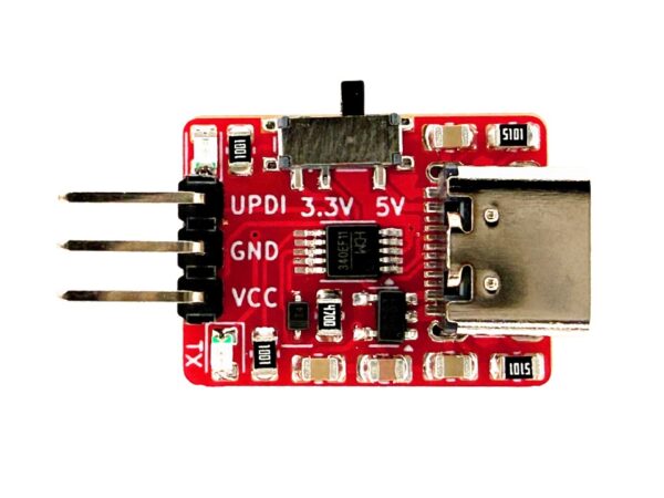
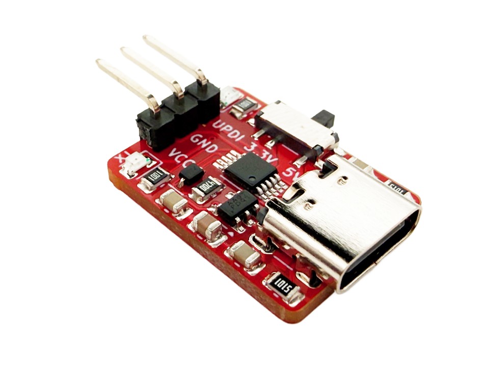
This UPDI programmer is great for programming the new ATtiny 0, 1 and 2 series microcontrollers. These microcontrollers are programmed with UPDI (Unified Program and Debug Interface) rather than ISP. It combines a CH340E serial converter with the correct components on the RX and TX lines to turn it into a UPDI programmer. It also has a 500mA output 3.3V regulator so you can switch between powering 5V and 3.3V devices. Programming microcontrollers is also made easier by the pre-soldered 2.54mm (0.1″) headers, its power selector switch, and its indicator LEDs. The male header pins can also fit standard female jumper wires.

UPDI Programmer 5V/3.3V
$5.95
Its features include:
- 3.3V or 5V selector switch
- 3.3V regulator can put up to 500mA
- Red power indicator LED
- Green active serial indicator LED
- CH340E serial converter with standard drivers
- USB-C connector
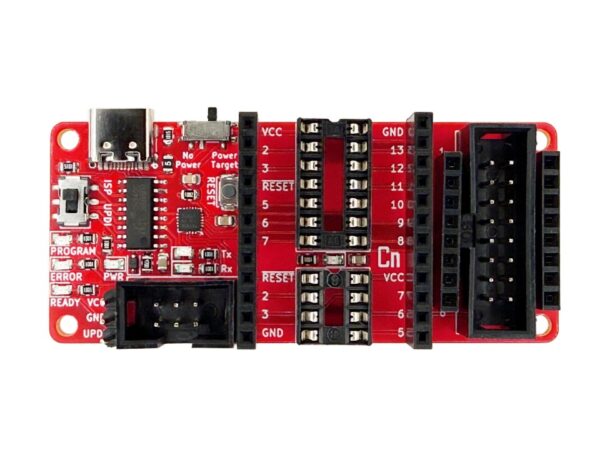
Layout/Pinout
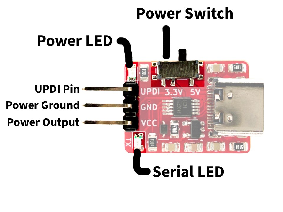
- UPDI Pin is the programming output of the board. You can connect it to the dedicated UPDI pin of your microcontroller. Its logic level is either 3.3V or 5V depending on what is selected by the power switch.
- Power Ground is the common ground for the entire board.
- Power Output is the output from the voltage regulator and USB port. It can be 3.3V or 5V depending on what is selected by the power switch. You can source 500mA from the 3.3V regulator or 500mA at 5V from the USB-C port.
- Power Switch is used to switch between 3.3V or 5V power and logic.
- Power LED will turn on when the board is powered.
- Serial LED will turn on while programming.
Wiring
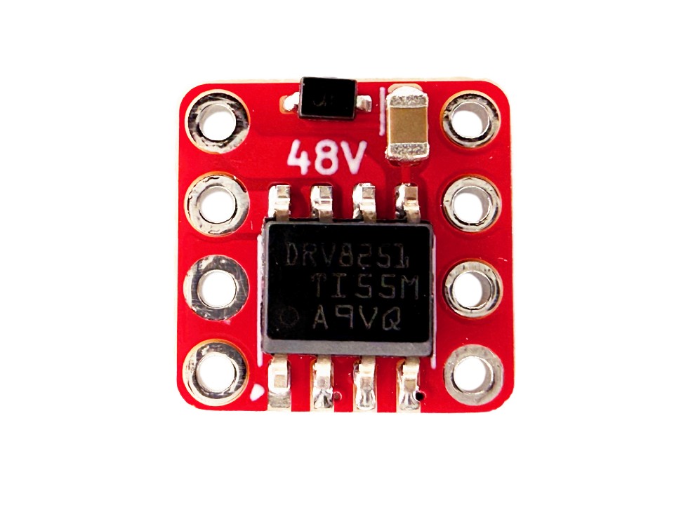
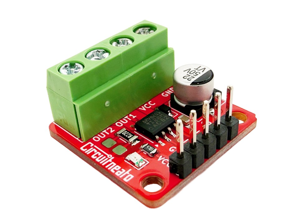
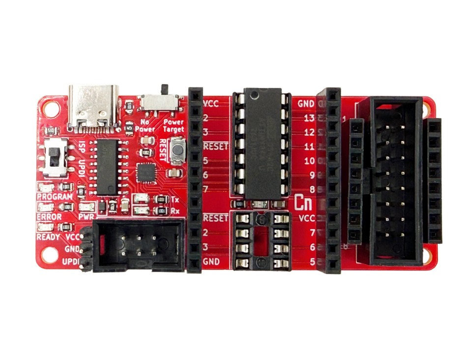
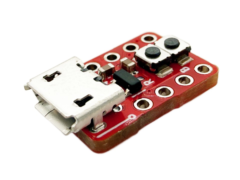
Wiring the programmer to a microcontroller board that has the UPDI pin broken out is easy. If you just have a standalone chip, you may want to solder on a breakout board which has 2.54mm (0.1″) headers so you can connect to the pins more easily. If you are using male or female headers you can use standard 2.54mm jumper wires to connect the programmer to them.
On the UPDI programmer, connect the pin labelled “UPDI” directly to the UPDI pin on your microcontroller, as well as the “GND” pin to the microcontroller’s ground, and the “VCC” pin to the microcontroller’s VCC.
megaTinyCore Setup
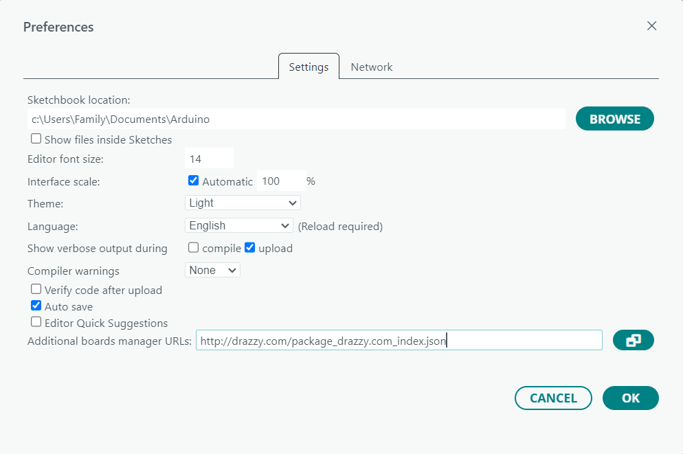
The megaTinyCore boards package adds support for the 0, 1, and 2 series ATtiny’s in the Arduino IDE. This allows for an easy way to program any of the ATtiny’s that support UPDI. To install the package, go to Tools > Preferences then paste the boards package URL listed below into the Additional Boards Manager URLs section. Make sure it is on a new line if necessary. While you are here, you may also want to check “Upload” for the “Show verbose output during” option. This will show the upload process in the output section at the bottom of the Arduino IDE screen, and it is helpful for debugging.
http://drazzy.com/package_drazzy.com_index.json
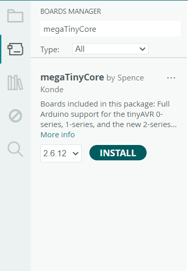
After this, go to Tools > Boards > Boards Manager and search for “megaTinyCore”. Then click install and let the package finish installing.
When you are ready to program, go to Tools > Board > megaTinyCore, and select the correct list that includes your chip. The options that include “w/Optiboot” allow you to burn the Optiboot bootloader using UPDI which gives serial programming support to the microcontrollers. When you upload code normally using these options, it will try to upload through a serial connection and UPDI won’t work. If you just want to upload code with the UPDI programmer, you can choose the options that don’t include “w/Optiboot”.
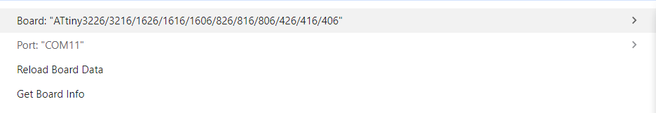
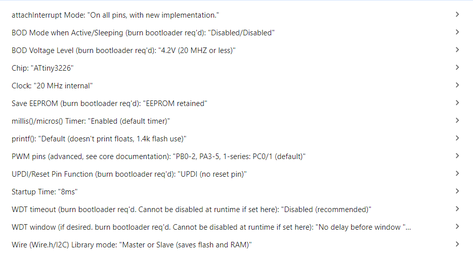
After you choose the correct list of chips, go back to the Tools tab and change the board options as needed. Change the Chip option to the specific chip you are using, which is the ATtiny3226 for us, and change the Clock option to whatever you want. If your board doesn’t have an external crystal, use one of the options marked “internal”. 20MHz or 16MHz are great for 5V devices, but if you are running your chip at 3.3V, use 10MHz, 8MHz or less. We will use 20MHz. BOD Voltage Level can also be changed depending on what voltage you are using, as long as you make sure to use the “Burn Bootloader” option at the bottom of the Tools menu. All other options shouldn’t need to be changed in most cases.
Finally, in the Programmer section, choose a SerialUPDI option. All the options that work with this programmer are listed below.
- SerialUPDI – 230400 baud
- SerialUPDI – SLOW: 57600 baud
- SerialUPDI – FAST: 4.5v+ 460800 baud (CH340 – and maybe some others)
- SerialUPDI – TURBO: 4.5v+ 921600 baud (CH340 (and maybe some others) only)
The FAST and TURBO options work for devices running at 5V, and any of the slower options will work for devices under 5V. If the fastest TURBO option is not reliable, try using a slower option. For our case, we will use SerialUPDI – TURBO: 4.5v+ 921600 baud (CH340 (and maybe some others) only)

Programming
We will upload a simple blink sketch to our board. This blink sketch will drive pin 3 high and low, which also happens to be connected to an LED on our Tineato 3226 boards.
void setup() {
  pinMode(3, OUTPUT);    // set pin 3 as an output
}

void loop() {
  digitalWrite(3, HIGH); // drive pin 3 high
  delay(1000);
  digitalWrite(3, LOW);  // drive pin 3 low
  delay(1000);
}
Now double check the connections from the chip to the programmer, and make sure the correct chip and options are still selected. You can upload the code simply by pressing the upload button at the top left of the IDE screen. If you checked “Upload” for the “Show verbose output during” option in the preferences menu, you should see a lot of red text in the output section.
During this time you can also click Burn Bootloader in the Tools menu if you have selected any options that require it, like BOD Voltage. If you selected a list of chips that can be programmed with Optiboot, you will need to burn the bootloader using the UPDI programmer before you can use the normal upload button to upload code through a serial converter.

Leave a Reply