This tutorial is for both of our FE1.1s based USB hub boards. You may want to use our Mini USB Hub board for adding extra USB peripherals to your project, or our larger USB Hub board with female USB ports for a DIY USB hub or a custom keyboard with free ports to connect devices to.
Mini USB Hub Pinout
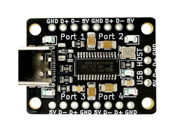
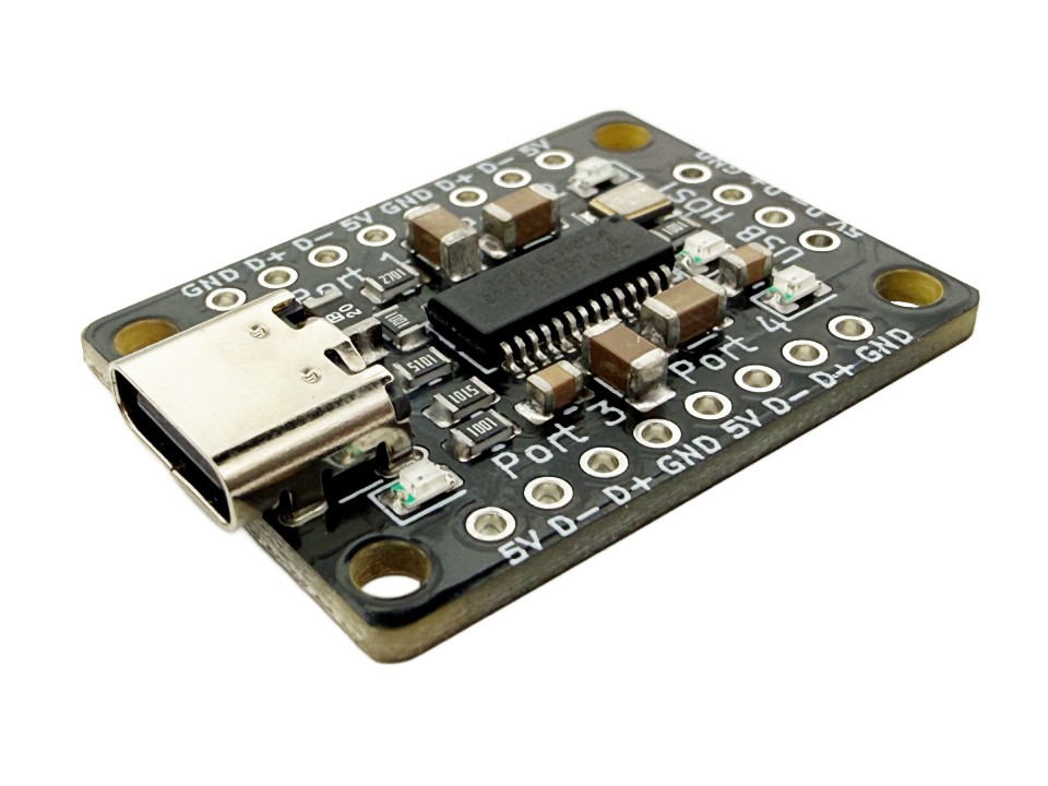
The Mini USB Hub has a simple pinout for each of the downstream ports.

There are 4 sets of 4 pads for each of the 4 downstream ports. These are what you can connect your USB devices to. Each are labeled by the silkscreen text Port 1, Port 2, Port 3, and Port 4. The pinouts for each port goes as follows:
5V5V output powerD-Data negativeD+Data PositiveGNDCommon ground
There is also a set of 4 pads labeled USB HOST which are the power and data lines from the upstream device (whatever is connected to the USB-C port). If you don’t want to use the USB-C port for the upstream host device, you can connect a device to these pads instead. The pinout for these pads are the same as above.
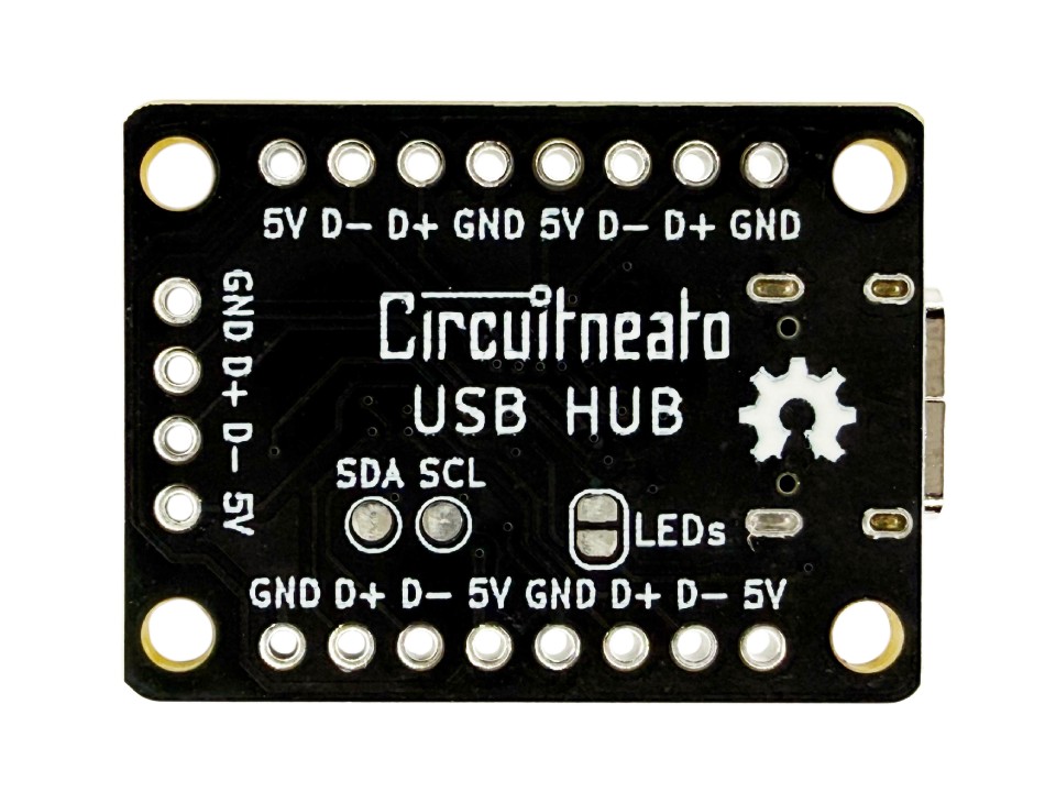
On the back of the board, there are two test points for SDA and SCL from the chip. These are for an external EEPROM chip to be connected. See more in the “Features” section.
USB Hub with Ports Pinout
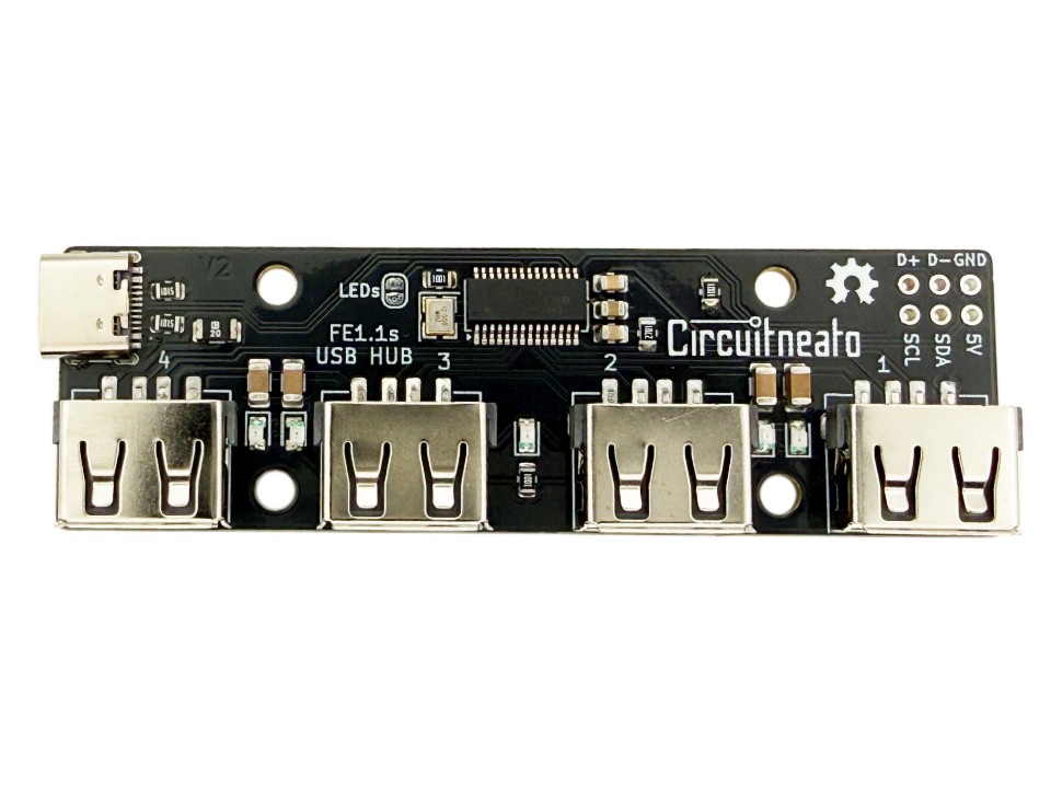
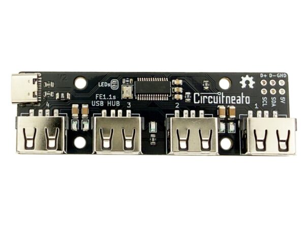
The USB Hub with the female USB-A ports has 6 pads for the USB host and an I2C connection to the FE1.1s controller. The 4 downstream ports are the female USB-A connectors. Each are labeled by the silkscreen text 1, 2, 3, and 4. The pinout for the group of 6 pads goes as follows:
D+Host data positiveD-Host data negativeGNDCommon ground5V5V Power OutputSDAFE1.1s I2C serial dataSCLFE1.1s I2C serial clock
The D+, D-, GND, and 5V pads can be used to connect and upstream host device to the board, if you don’t want to use the USB-C port. The 5V and GND pads can also be used to power the board without using the USB port.
Like for the Mini USB Hub, the SDA and SCL pads are for an external EEPROM chip to be connected. See more in the “Features” section.
Usage
You should not need to download any extra drivers for these USB hubs as they act as generic USB 2.0 hub controllers. You can simply use a USB cable with a USB Type-C connector on one end to plug into the USB-C port on the hub. It should connect to your computer and the red LED will blink once. Once connected, you can connect the downstream devices to the ports on the USB hub like headphones, keyboards, or any other USB enabled devices. These devices should connect as they would to your computer directly. If you have the mini version without the USB-A connectors, you can solder the data and power USB lines from the device to the pads for one of the ports.
Features
Both USB hubs come in self-powered mode by default. This means that the board can supply up to 500mA to all of the downstream ports individually, 2A combined. If the upstream device can’t support up to 2A to the USB hubs, then power can be supplied from an external power supply to the 5V and GND pins. If you want to power the USB Hub with Ports externally while having an upstream device connected to the USB port, then the “Disable USB Power” jumper should be cut to avoid backfeeding power.
An external EEPROM board or chip can be connected to the broken out SDA and SCL pins. The EEPROM can be used to change the product ID, vendor ID, or the device release number. (See page 15 of the FE1.1s datasheet linked at the bottom of this post.)
LEDs and LED jumper
On each of the boards, there are 4 green LEDs and one red LED. The green LEDs indicate which of the downstream ports are connected. On the Mini USB Hub, the LEDs are located next to the PORT # labels. On the USB Hub with female ports, the LEDs are located closest to each USB-A port. These green LEDs will turn on when their respective downstream device is connected.
The red LED indicates if the USB host device is connected. It is located above the USB HOST text on the Mini USB Hub, and in the middle of all of the USB-A ports on the other board. The red LED will blink once when the USB Host connects, then stay on when one or more downstream devices are connected.
The jumper labeled “LEDs” on both of the boards can be cut with a knife to disable all of the onboard LEDs.
Revisions
On the original red version of both USB hubs, the chip is set to bus-powered mode, which allows up to 500mA to all of the downstream ports combined. This can be changed to self-powered mode on the USB Hub with Female Ports by shorting the “POW” jumper with solder. Self-powered mode allows 500mA to each of the downstream ports, for 2A total.

Leave a Reply