This is a simple, versatile, and powerful motor driver that can be used for almost any of your robotics projects. The board is based around the DRV8251 H-Bridge motor driver, allowing for a 3.7A peak current (~2.3A continuous) and 4.5V-48V supply voltage range. This driver can be used for almost any brushed DC motor because of its wide voltage range and current capabilities.
Features
Here are the features of the DRV8251 H-bridge driver chip:
- 4.5V-48V supply voltage
- 3.7A Max, ~2.3A continuous
- 2.3A current limit at 5V logic
- 1.5A current limit at 3.3V logic
- PWM control up to 200KHz
- 1.5V-5.5V logic voltage
- 450mΩ RDS(on)
- Overcurrent protection
- Thermal shutdown
- Undervoltage lockout
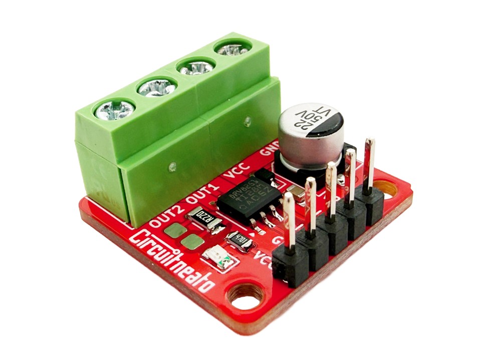
The board also includes screw terminals and 2.54mm (0.1″) male headers for easy wiring, a current limit resistor along with space to solder a different one, a power indicating LED, and a protection diode.
Layout
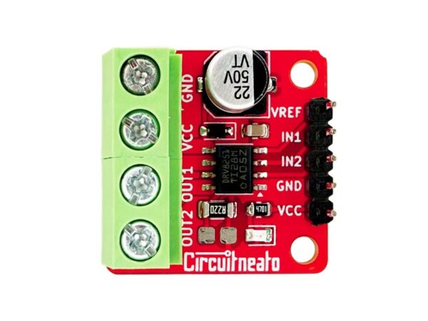
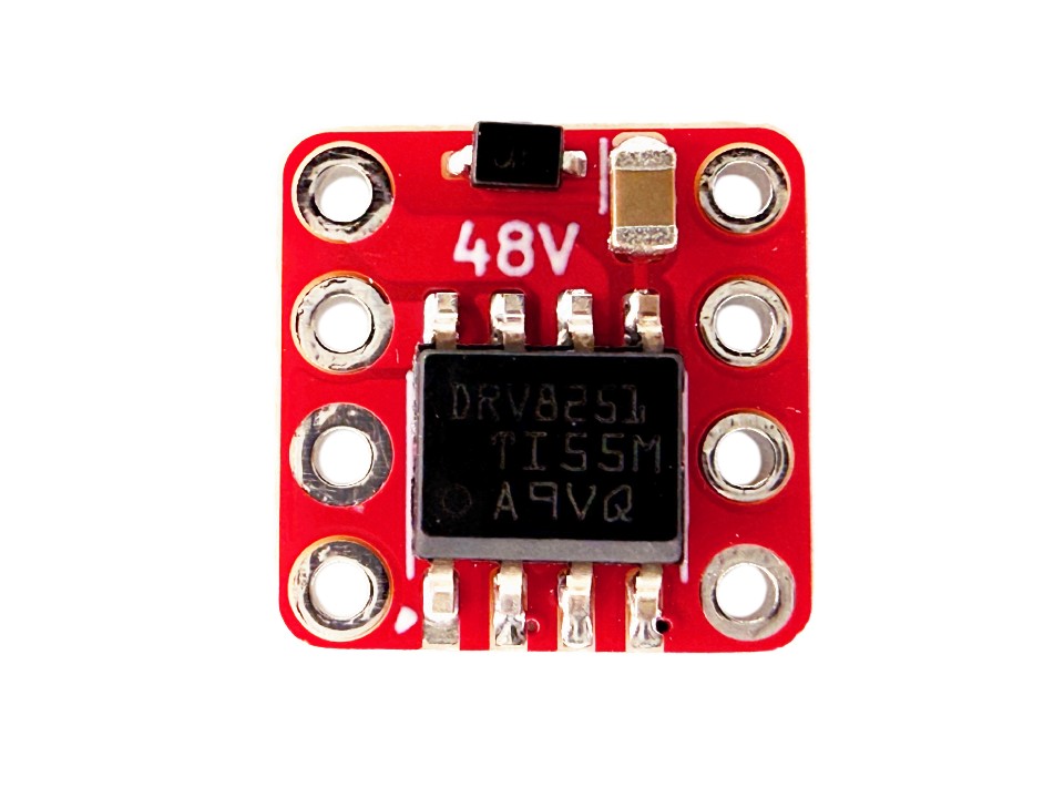
The board has simple silkscreen markings for each of the pins on the top of the board. There is also text on the back to show simple specs of the board for quick reference.
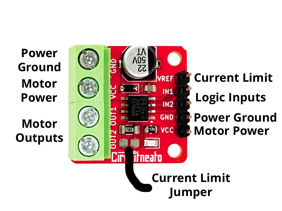
- Power Ground is the common ground bus on the whole board. It is the logic ground to the motor driver chip, and also the ground to your motor power supply.
- Motor Power is the supply pin for the motor outputs which can support 4.5V to 48V. The screw terminal is internally connected to the Motor Power pin on the 2.54mm header strip, so you can connect your power supply to either one.
- Motor Outputs are the output pins from the driver chip. These are where you should connect the two leads/wires of a brushed DC motor to. Which way you connect the leads of the motor does not matter, it will only reverse the default spinning direction.
- Logic Inputs are the control inputs used for the motor driver. IN1 relates to OUT1 and IN2 relates to OUT2. These pins support 1.5V-5.5V, and a max frequency of 200KHz.
- Current Limit is a necessary pin for the current limiting resistor reference voltage. This pin can support 0.3V to 5V, and does not have to be the same voltage as the logic input pins. See more about this pin in the section below.
Current Limit
A 0.22 ohm resistor is used on the board for current limiting. There is a space beside the resistor to either solder a different resistor, or short over with solder to not have a current limit. To make the current limit work, a voltage must be supplied to the VREF pin.
The voltage on this pin will change the current limit, so at 5V the current limit will be 2.3A, and at 3.3V the current limit will be 1.5A. If you don’t want a current limit and you shorted over the resistor, you will still need to supply a voltage between 0.3V to 5V (higher is better). To calculate the current limit with the VREF voltage, use this formula: Limit = VREF / 2.2
Usage
Start by connecting two digital output pins from a microcontroller to IN1 and IN2. You can just use HIGH or LOW outputs, but if you want PWM speed control, these pins should be PWM capable. Then connect a voltage to the VREF pin as stated in the last section. This can be from a low power supply like the 5V pin on an Arduino UNO. After this, connect your high power supply 4.5V – 48V to VCC and GND, and your motor wires to OUT1 and OUT2.
The code below will spin the motor one direction at full speed for 2 seconds, spin the motor the other way at about half the speed for 2 seconds, then repeat. If you set both outputs to HIGH at the same time, you can make the motor stop quickly by making it act like a generator and have a braking effect. If you need to run the motor slower than full speed, you can use a PWM function in the Arduino IDE like analogWrite(IN1, 200);
const int IN1 = 0;
const int IN2 = 1;

void setup() {
  pinMode(IN1, OUTPUT);
  pinMode(IN2, OUTPUT);
}

void loop() {
  //turn motor one direction at full speed
  digitalWrite(IN2, LOW);
  digitalWrite(IN1, HIGH);
  delay(2000);

  //turn motor the other direction about half the speed
  analogWrite(IN2, 127);
  digitalWrite(IN1, LOW);
  delay(2000);
}

Leave a Reply