


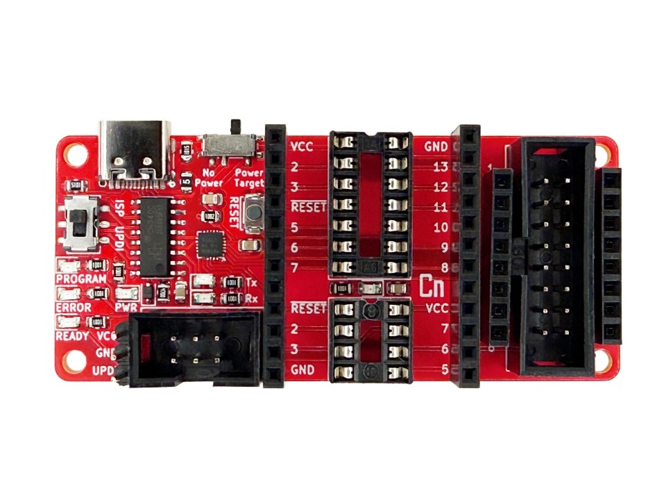
This is an easy to use and versatile programmer for all sorts of AVR microcontrollers. It is great for classic ATtiny’s like the ATtiny85 and ATtiny84, but also for newer 0, 1, and 2 series ATtiny’s like the ATtiny3226. Most ATmega microcontrollers can also be programmed like the ATmega328. Prototyping within the programmer is also made easy by female header strips that can accept standard male jumper wires.
Features
The programmer is full of different features that make using it easier. Some of these features include:
- USB-C port
- 500mA polyfuse protected power
- Power switch
- Protocol switch
- Reset button
- 7 LEDs including LED_BUILTIN
- 3 pin UPDI header
- 6 pin ISP header
- DIP-8 socket
- DIP-14 socket
- 16 pin header for SMD clips
- Female header strips for prototyping
- 4 mounting holes
All of the different chip mounting options allow for versatility and easier programming. You can fit DIP devices up to DIP-14 in the two DIP sockets, and you can also fit various other adapters for SMD parts into them. The 16 pin shrouded header can fit an SMD clip which allows for an easy way to program SOIC package chips up to SOIC-16. The clip can also be connected to chips on or off a PCB. Beside these connectors, there are strips of female headers that are directly connected to their respective pins. You can fit jumper wires into these headers for prototyping without having to remove the chip.
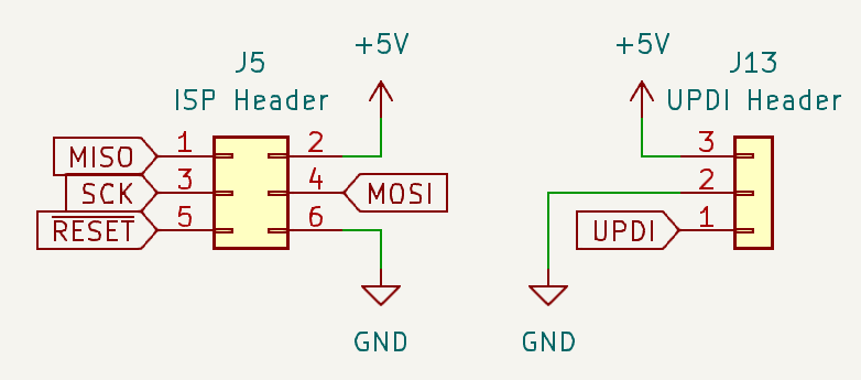
The 6 pin shrouded header is made for ISP cables, which allows for you to easily program boards that also have an ISP connector, like an Arduino UNO. Next to it is the 3 pin UPDI header which can be used to program UPDI devices off the programmer board.
Layout
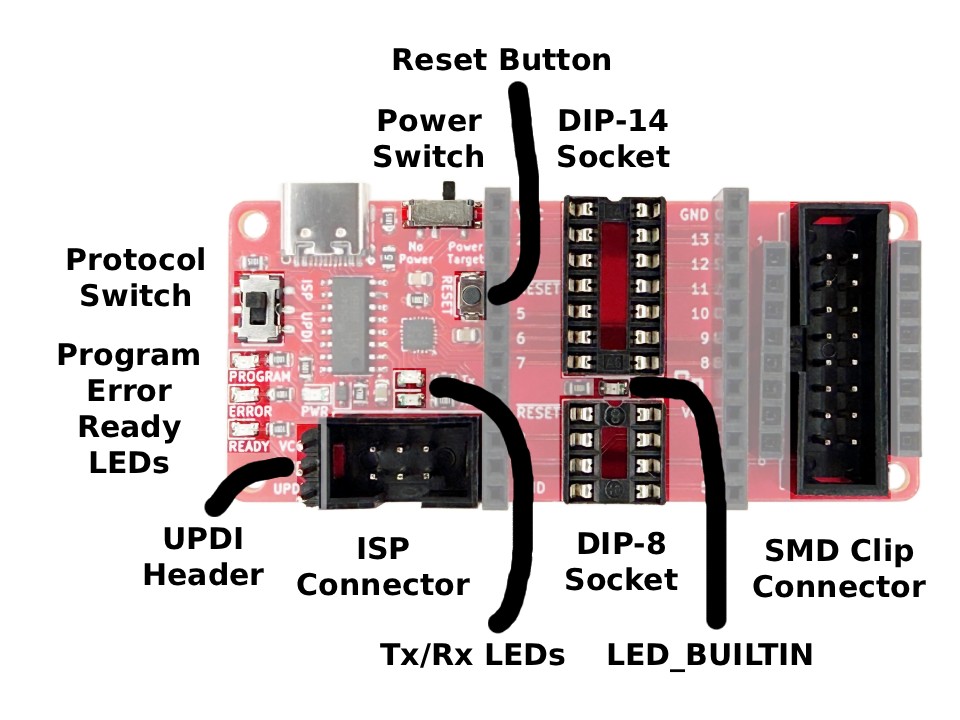
- Power Switch allows you to power the target device, or disconnect it from power. This can be useful for power resetting a chip, or if you are powering the target with an external power supply while the USB port is connected.
- Protocol Switch allows you to switch between ISP programming and UPDI programming. If you are trying to program a UPDI chip, you will need to switch to UPDI, and vice versa for ISP.
- Reset Button is a quick way to reset target chips that support it. You can check the pinout of the specific chip you are programming to see if its reset pin lands in the correct spot on one of the connectors.
- UPDI Header can be connected to 2.54mm (0.1″) female jumper wires for programming UPDI devices not on the programmer board. These devices may have a similar three pin header that can be wired to this one.
- ISP Connector is a 2×3 pin connector made to fit ISP cables, which allows for you to easily program boards that also have an ISP connector, like an Arduino UNO.
- DIP-8 Socket can fit DIP-8 chips like the classic ATtiny85/45/25, as well as the ATtiny13. Check the pinout of any other chips to see if they are compatible.
- DIP-14 Socket can fit DIP-14 chips like the ATtiny84/44/24. Check the pinout of any other chips to see if they are compatible.
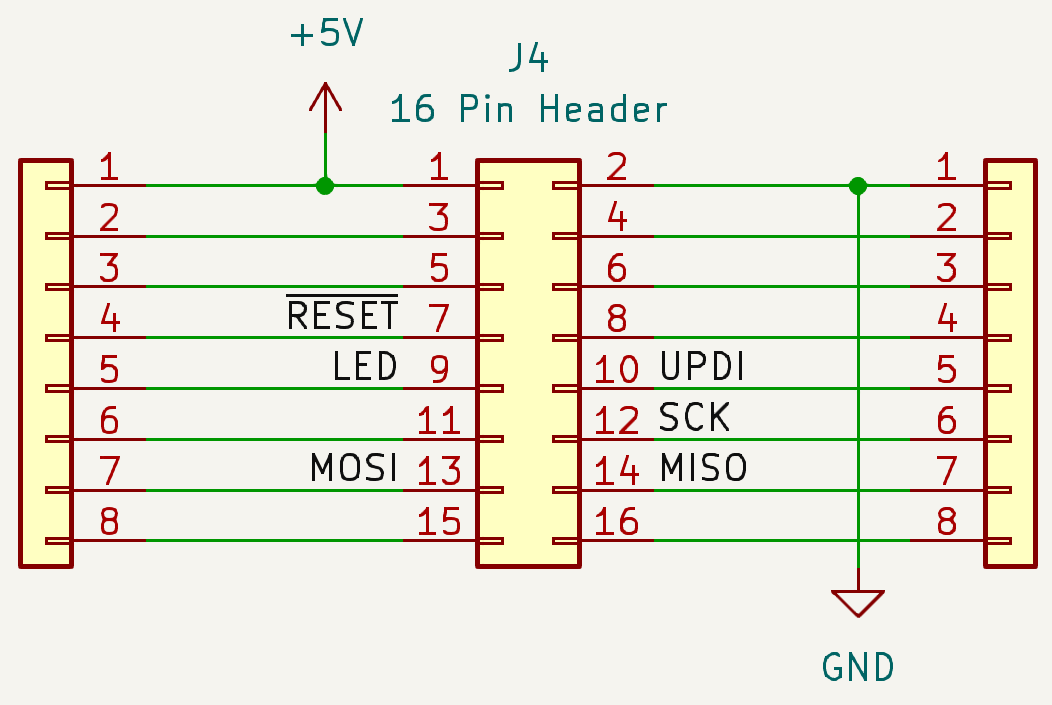
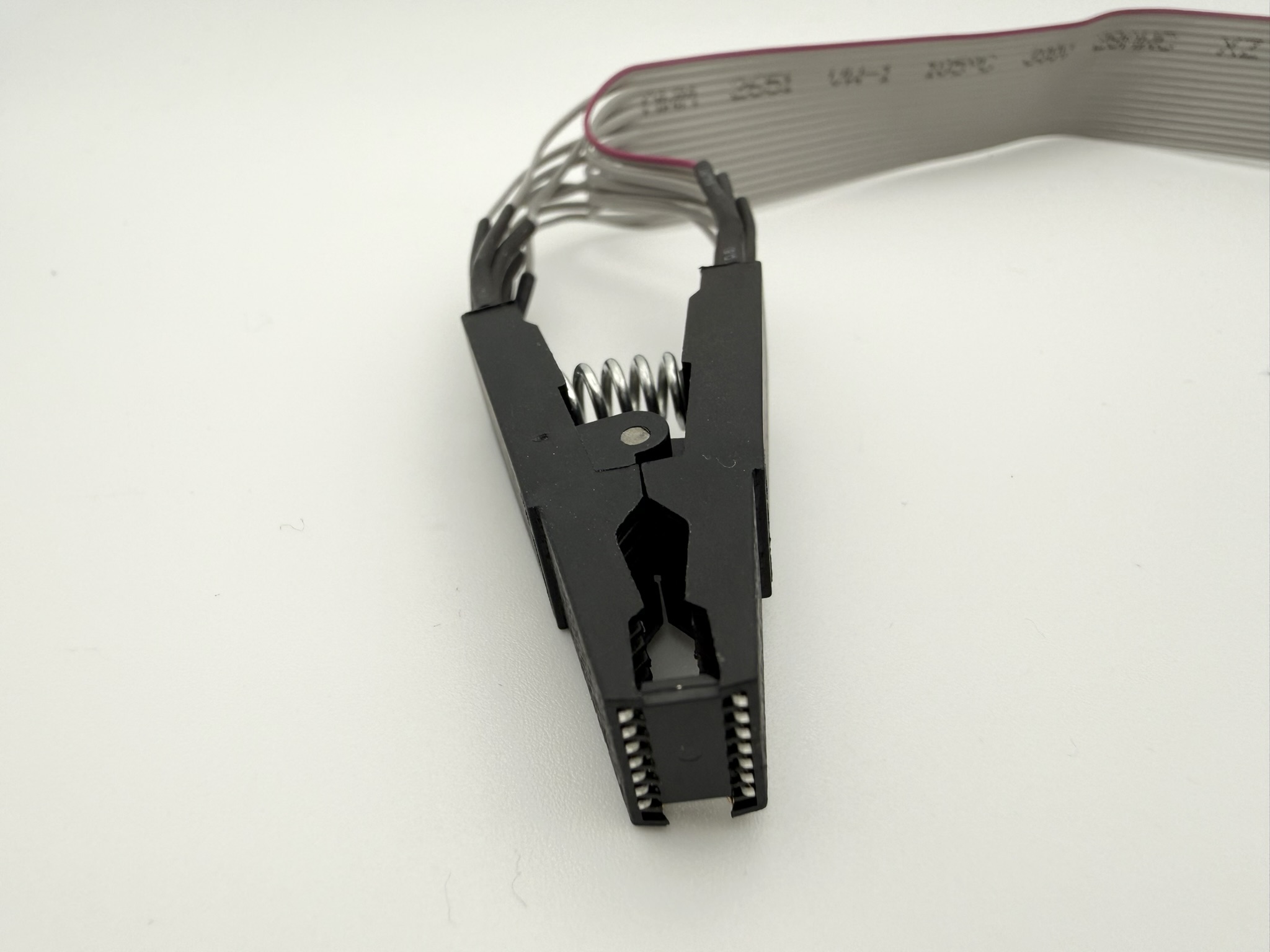
- SMD Clip Connector is a 2×8 pin connector that can fit our SOIC-16 clips. These clips can attach to many different chips in narrow and wide body SOIC packages, some of which include: ATtiny84/44/24, ATtiny841/441, ATtiny1604/804/404/204, ATtiny1606/806/406, ATtiny1614/814/414/214, ATtiny3216/1616/816/416, ATtiny3224/1624/824/424, and ATtiny3226/1626/826/426.
- Prototyping Headers are strips of female headers on either side of the DIP sockets and on either side of the SMD clip header. Their pins are directly connected to the respective pins on the connectors.
- LEDs
- Program LED flashes yellow while ISP programming is happening.
- Error LED flashes red if there is a problem while ISP programming.
- Ready LED flashes green when ISP programming is ready. The program, error, and ready LEDs are only used for ISP programming and not for UPDI.
- Tx/Rx LEDs flash during UPDI programming, and before ISP programming starts.
- LED_BUILTIN is an LED that is connected to pin 5 of the DIP-14 socket, and pin 5 of the SMD clip header. It can be controlled by the microcontroller getting programmed for prototyping debugging. You can check megaTinyCore, ATTinyCore, or whatever boards package you are using to see if one of the I/O pins is named LED_BUILTIN. If that pin lands on pin 5 on the usable connectors, it can control the LED. Otherwise, you can call the correct pin name directly.
Pinout
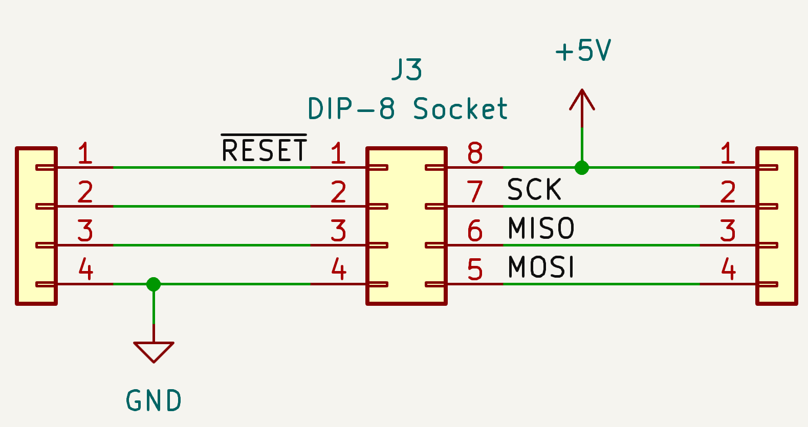
Below is the pinout for the DIP-8 socket. Notice how each of the 8 pins connects to strips of female headers on either side. Pin 1 connects to the reset pin for ISP programming as well as the reset button, and pins 5, 6, and 7 connect to the ISP programming pins MOSI, MISO, and SCK respectively. Pin 4 connects to ground, and pin 8 connects to the 5V source. There is no connection to the LED_BUILTIN LED on the DIP-8 socket.
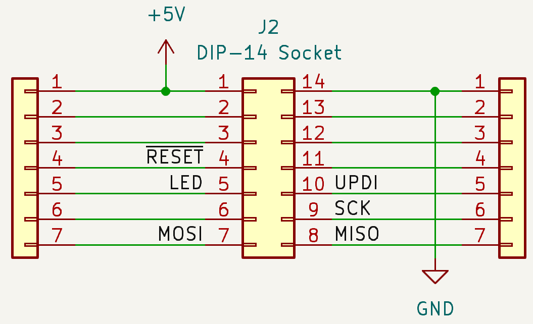
Below is the pinout for the DIP-14 socket. All of its pins are also broken out to 2 strips of female headers on either side. Pin 4 connects to the reset pin for ISP programming as well as the reset button, pin 5 connects to the LED_BUILTIN LED, and pins 7, 8, and 9 connect to the ISP programming pins MOSI, MISO, and SCK respectively. Pin 1 connects to the 5V source, and pin 14 opposite of it connects to GND. The DIP-14 socket also has the UPDI programming circuitry connected to pin 10.
The 16 pin SMD clip connector has the same pinout as the DIP-14 socket, but with two extra optional pins (15 and 16). This allows you to use the SMD clip for SOIC-14 chips even though it has 16 pins. Notice that the pin numbers are labeled odd/even rather than counter clockwise to match the pinout of the SMD clip.
The ISP connector and UPDI header have silkscreen pin markings on the front and back of the programmer board.
Usage with Arduino IDE
The All In One ATtiny Programmer is easy to use in the Arduino IDE. Depending on the chips you want to program, you will need to download a boards package that includes support for it. This could include megaTinyCore, ATTinyCore, MiniCore, MightyCore, MegaCore, and more.
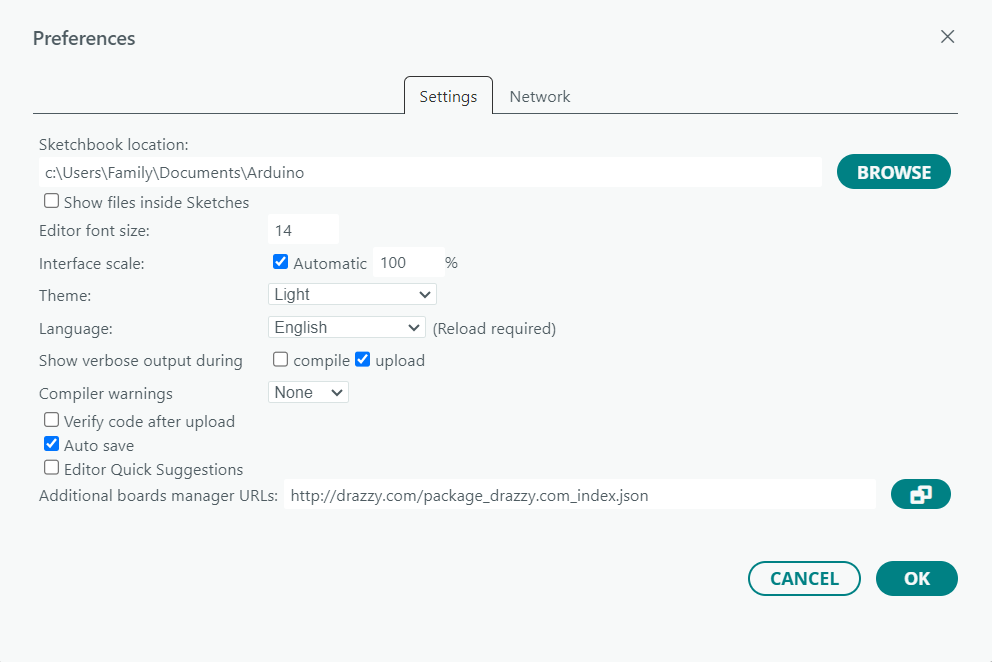
As an example, follow these directions to install megaTinyCore (which gives support for newer ATtiny 0, 1, and 2 series chips) and/or ATTinyCore (which gives support for most classic ATtiny chips) First, go to File > Preferences then next to “Additional boards manager URL’s” enter this: http://drazzy.com/package_drazzy.com_index.json (making sure it is on a new line if necessary).
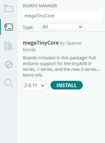
Then go to the boards manager from Tools > Board > Boards Manager and search for either “megaTinyCore” or “ATTinyCore“. You can then click install for the core you want or both.
After they install, go into Tools > Board > megaTinyCore or Tools > Board > ATTinyCore and select the chip you want to program, along with its options.
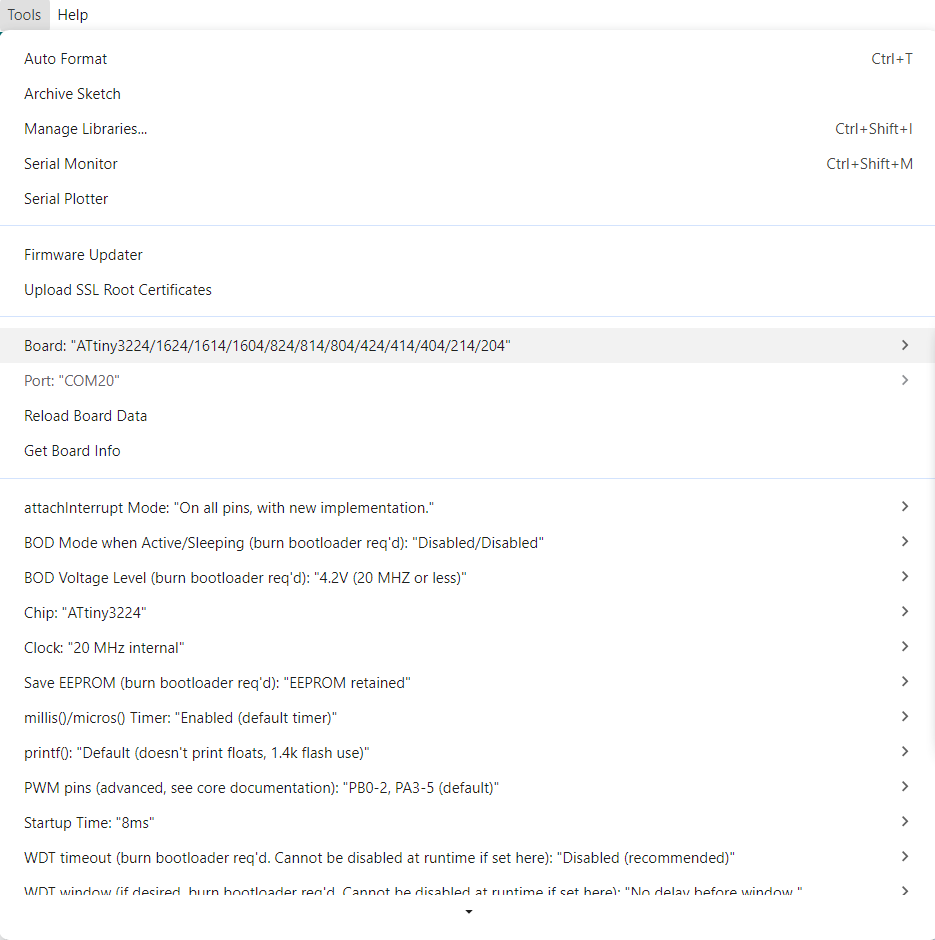
For most AVR microcontrollers you can write code in the Arduino IDE like you would for any classic Arduino development board, with most libraries still being compatible. megaTinyCore and ATTinyCore also include some edited libraries that otherwise wouldn’t have been compatible.
MiniCore is a great package for ATmega328/168/8 devices, and MightyCore is a great package for ATmega16/32/644/1284 devices. MegaCore is great for almost any other ATmega device like the ATmega2560. These can be installed the same way as the last two boards packages, but require different links in the preferences menu:
- MiniCore:
https://mcudude.github.io/MiniCore/package_MCUdude_MiniCore_index.json - MightyCore:
https://mcudude.github.io/MightyCore/package_MCUdude_MightyCore_index.json - MegaCore:
https://mcudude.github.io/MegaCore/package_MCUdude_MegaCore_index.json
If you need support for other chips not included in these packages, you can find other boards packages online and read their instructions on how to install them. Some chips like the ATmega32U4 are included by default in the Arduino IDE, but are called “Arduino Leonardo”. This option allows you to program ATmega32U4 chips without needing to install anything extra, but they will follow the same pinout as Arduino Leonardo boards.
Programming Information
The first step is to know the chip you are using. You will want to know its name/part number and find its datasheet. All datasheets for AVR chips can be found on Microchip Technology’s website. The connectors on the programmer give you many options for ways to connect to chips. See the Layout section above to see examples of chips that fit into the connectors on the board. For other devices, you can check its respective datasheet to see if the package and/or pinout is directly compatible with the connectors on the board.
External Adapters
If you have a chip that is not compatible, you can use SMD adapters that connect to standard 2.54mm jumper wires to connect to either the ISP header, or the UPDI header on the programmer. An example of an SMD adapter is our SOIC-16 Test Clip which you can connect to the correct pins on your chip. This clip can be inserted into the 16 pin header on the programmer, but for incompatible chips you can instead use standard jumper wires that connect from the header end of the clip to the programmer. Using jumper wires in this way allows you to connect the correct pins from the chip to the programming pins on the programmer.
Most ATmega chips cannot directly connect to any of the connectors on the programmer, either because of their package or because of their pinout. For DIP ATmega chips, you can directly connect jumper wires to their pins. But for any standalone SMD chips you will need to use another type of SMD adapter, unless the chip is already soldered to a breakout board or development board.
Protocol and Reset
If you are using a device that is programmed by a UPDI pin, make sure to flip the protocol switch to the UPDI setting. If you are using a device that is programmed by ISP, flip the switch to the ISP setting. The onboard reset button connects to all of the pins labelled “RESET” on the target device connectors. These are strategically placed so that this reset button works with many chips that directly fit in the connectors. You can check the pinout of your chip to see if its reset pin falls in the same spot as the ones on the programmer. If it does, you are able to press the button to reset it.
Power Supply
For most cases, you will want the power switch to be set to “Power Target” so that the programmer self powers the chip without the need for an external supply. If you are powering the target device with an external power supply, flip this switch to the “No Power” position so that both sources don’t short circuit. This switch can also be used to power reset the target device by flipping it off and back on, given that it is self powered. If you are using an external power supply, make sure it is a regulated 5V as any voltage lower or higher can damage the target chip and/or the programmer.
Oscillators
This programmer does not include external timing crystals for the target device, instead, the internal oscillator(s) in the AVR chip you are programming is used. Some older AVR chips have oscillators tuned to 3.3V with a low tolerance. This means at 5V the internal oscillator can sometimes be too far off from its speed rating, and not be able to be programmed reliably.
To fix this you can use an external 16MHz crystal and use the respective female prototyping pins to connect the external crystal. The two pins of the crystal connect to the XTAL1 and XTAL2 pins of the chip (no specific polarity, you can find these pins in the chip’s pinout). Then use the two 22pF capacitors to connect between ground and both pins of the crystal individually.
LED_BUILTIN
This is an LED that can be used for debugging from the target device. The DIP-14 connector and 16 pin connector each have a pin that is connected to this LED, which is labelled “LED” on the bottom of the board. In your code you can control this pin by driving the correct I/O pin high or low. You may need to check the pinout of your chip to make sure the respective pin is a free I/O pin. Some cores like megaTinyCore and ATTinyCore support calling it “LED_BUILTIN” in the Arduino IDE, but you may need to double check that pin is in the right spot.
Jumpers
There are five solder jumpers on the bottom side of the programmer.
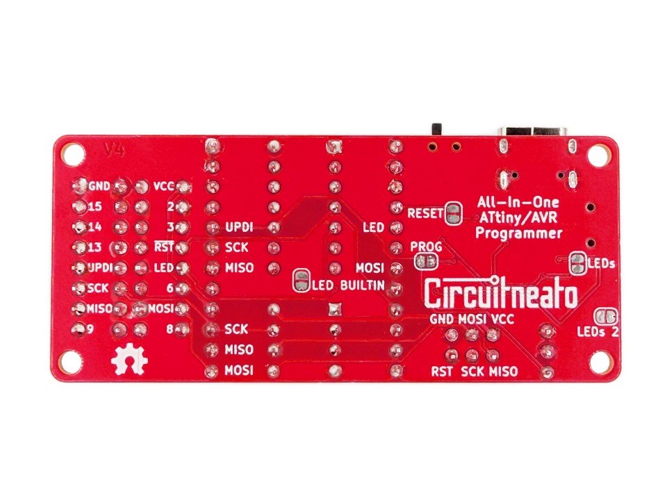
All of them besides the PROG jumper, (as it is already disabled), can be cut with a knife between the two silver pads to disable their functions. The LEDs jumper disables the program, error, and ready LEDs. The LEDs 2 jumper disables the Power, TX, and RX LEDs. The LED BUILTIN jumper disables the LED_BUILTIN LED in case you don’t want it messing with the corresponding I/O pin on the target device.
The RESET jumper disconnects the 10K ohm resistor connected to all of the target device reset pins, in case you don’t want it. And finally, the PROG jumper can be bridged with solder to be able to re-program the onboard ATtiny806 programming chip. It connects to the UPDI circuitry coming off the serial converter, but shouldn’t need to be used for normal usage.
Programming Examples
Example 1 ATtiny84
For our first example we will program a DIP-14 ATtiny84 in the DIP-14 socket. Start by pushing the chip into the socket, making sure its orientation dot faces the cutout in the socket so it is the right way around. Then double check the power switch is at the “Power Target” position, and the protocol switch is at the “ISP” position.
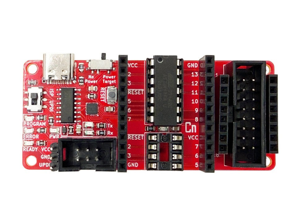
Now use any USB cable with a USB-C end to connect the programmer to your computer. Open the Arduino IDE and under the “Select Board” menu select the port which the programmer is connected to, if it doesn’t already show as connected. (The name may be different than shown below, like “Unknown” for example.)
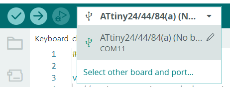
Then go to Tools > Board > ATTinyCore as installed earlier. Choose the “ATtiny24/44/84(a) (No bootloader)” option, or the specific chip you are using (The Optiboot and Micronucleus options work too if you need uploading through software serial or USB). After that, go to Tools > Programmer and choose “Arduino as ISP“.
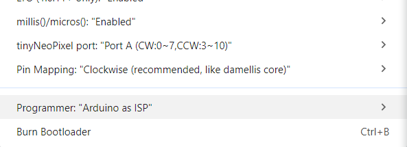
This gets you setup to program your chip. The code we will use is a simple blink sketch which will blink the LED_BUILTIN LED.
void setup() {
  pinMode(LED_BUILTIN, OUTPUT);
  // or you can change LED_BUILTIN to the specific pin the LED is connected to
}
void loop() {
  digitalWrite(LED_BUILTIN, HIGH);
  delay(1000);
  digitalWrite(LED_BUILTIN, LOW);
  delay(1000);
}
When you are done writing your code you can press the upload button as normal, and the program indicator LEDs will start blinking. Once it is done programming, the yellow LED_BUILTIN LED should start blinking once every second.
If you get any errors, check that the chip is connected properly, and is fully seated in the socket. Also check that the protocol switch is set to ISP, and the power switch is set to Power Target. In the Arduino IDE, you can check that your chip options are set correctly in the Tools menu. If you have an older system, you may need to download CH340 serial converter drivers which can be found here.
Example 2 ATtiny85
For our second example we will program a DIP-8 ATtiny85 in the DIP-8 socket. Similarly to the ATtiny84, push the chip into the socket, making sure its orientation dot faces the cutout in the socket so it is the right way around. Then like above, check the power switch is at the “Power Target” position, and the protocol switch is at the “ISP” position.
Now use any USB cable with a USB-C end to connect the programmer to your computer. Open the Arduino IDE and under the “Select Board” menu select the port which the programmer is connected to, if it doesn’t already show as connected. (The name may be different than shown below, like “Unknown” for example.)
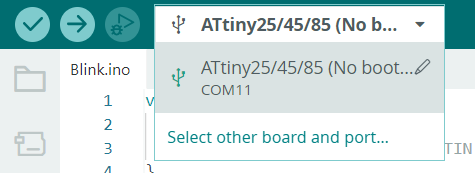
Then go to Tools > Board > ATTinyCore as installed earlier. Choose the “ATtiny25/45/85 (No bootloader)” option, or the specific chip you are using (The Optiboot and Micronucleus options work too if you need uploading through software serial or USB). After that, go to Tools > Programmer and choose “Arduino as ISP“.
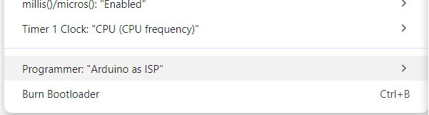
This gets you setup to program your chip. The code we will use is a simple blink sketch, but since there is no pin for the LED_BUILTIN LED on the DIP-8 socket, we will use a random I/O pin instead.
void setup() {
  pinMode(3, OUTPUT);
}
void loop() {
  digitalWrite(3, HIGH);
  delay(1000);
  digitalWrite(3, LOW);
  delay(1000);
}
When you are done writing your code you can press the upload button as normal, and the program indicator LEDs will start blinking.
If you get any errors, check that the chip is connected properly, and is fully seated in the socket. Also check that the protocol switch is set to ISP, and the power switch is set to Power Target. In the Arduino IDE, you can check that your chip options are set correctly in the Tools menu. If you have an older system, you may need to download CH340 serial converter drivers which can be found here.
Example 3 ATtiny3224
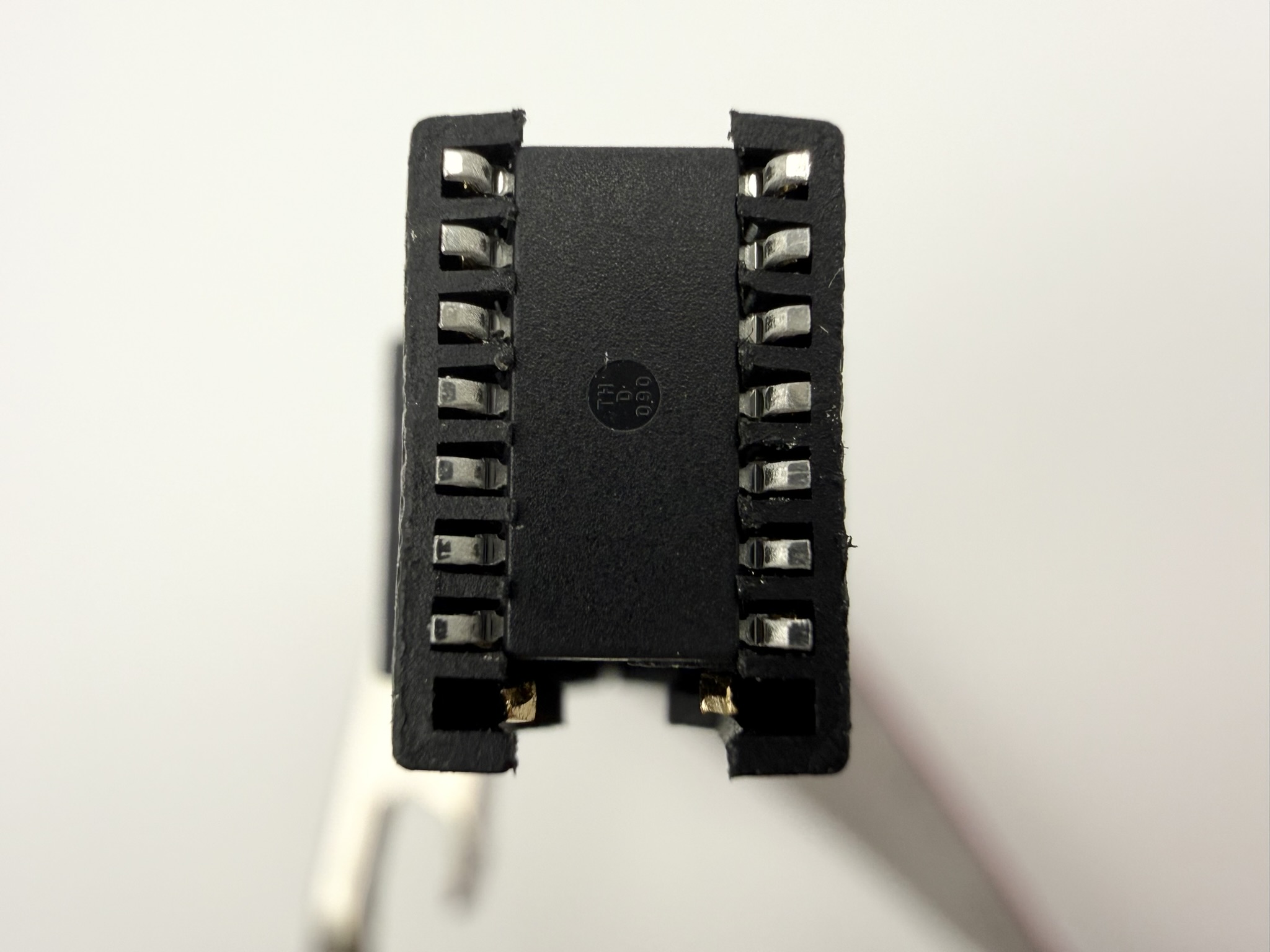
For our third example we will program a SOIC-14 ATtiny3224 using the SMD clip. Start by connecting the clip to the programmer’s 16 pin header. Since the clip has 16 pins and the chip is 14 pins, make sure the top edge of the chip is at the pin 1 side of the clip (red wire marks pin 1). This will leave two open pins on the clip past the bottom edge of the chip (see image below).
Then carefully place the clip over the ATtiny3224 from the top, making sure that all of the gold contacts touch the pins and the plastic teeth grip under the chip (see images below). Like last example, check that the power switch is at the “Power Target” position, but this time put the protocol switch to the “UPDI” position.
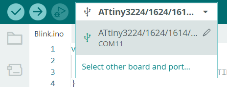
Now use any USB cable with a USB-C end to connect the programmer to your computer. Open the Arduino IDE and under the “Select Board” menu select the port which the programmer is connected to, if it doesn’t already show as connected. (The name may be different than shown below, like “Unknown” for example.)
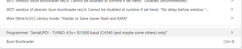
Then go to Tools > Board > megaTinyCore as installed earlier. Choose the “ATtiny3224/1624/…” option, or the specific chip you are using (The Optiboot options work too if you need serial programming support). Make sure you check all the other board options in the Tools menu, and make sure that the specific chip is correct. After that, go to Tools > Programmer and choose “SerialUPDI – TURBO: 4.5v+ 921600 baud (CH340 (and maybe some others) only)“. The other SerialUPDI options work too including:
- SerialUPDI – 230400 baud
- SerialUPDI – SLOW: 57600 baud
- SerialUPDI – FAST: 4.5v+ 460800 baud (CH340 – and maybe some others)
- SerialUPDI – TURBO: 4.5v+ 921600 baud (CH340 (and maybe some others) only)
We will use the same blink sketch from the last two examples. When you are ready, press the upload button as normal, and the Tx/Rx LEDs will start blinking. Once it is done programming, the yellow LED_BUILTIN LED should start blinking once every second. Since we are using the UPDI protocol rather than ISP, the 3 programming LEDs wont change while programming.
If you get errors when uploading, check the connection from the clip to the chip. Also make sure if you are using a different chip that its pinout matches the pinout of the 16 pin header. In the Arduino IDE, you can check that your chip and programmer options are set correctly in the Tools menu. As said in the last example, If you have an older system, you may need to download CH340 serial converter drivers which can be found here.
Leave a Reply