


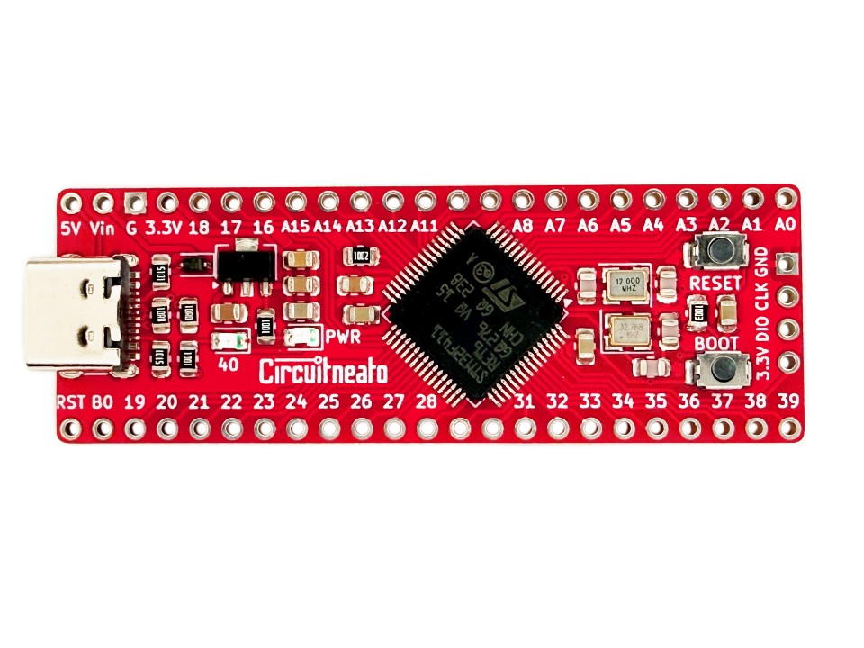
The STM32 Stick is a powerful development board in a breadboard compatible form factor, giving you 40 GPIO pins to work with. It uses the STM32F411RET6 running at 100MHz, with 512KB of flash memory, and 128KB of SRAM. The microcontroller comes with the DFU bootloader, which makes uploading code easy and allows the board to act as a HID device. 28 of the 40 I/O pins are PWM capable, and 16 have ADC support. There are also many communication peripherals available on pins including UART, I2C and SPI.
Features
The board includes a 3.3V regulator that can be used to power itself through the USB-C port or with a power supply up to 24V and output up to 500mA on the VCC pin. There are 40 pins total, 16 of which can be used as analog inputs, and 28 are PWM capable. Many of the pins also support UART, I2C or SPI. There is a red power indicator led, and a yellow LED_BUILTIN LED on pin 40.
On the back of the board is a footprint for you to solder on a 208mil SOIC-8 SPI flash memory chip, which is great if you need to store files or data. The STM32F411RET6 has built in USB functionality which works for uploading code through the USB port, and for acting as an HID device. Along with a reset and boot button for easier uploading. More of the STM32F411RET6’s features include:
- Cortex-M4 with FPU, 100MHz
- 512KB flash memory, 128KB SRAM
- 12 bit ADC
- UART, I2C, SPI
- DFU bootloader
- USB 2.0 full-speed device/host/OTG controller with on-chip PHY
Layout and Pinout
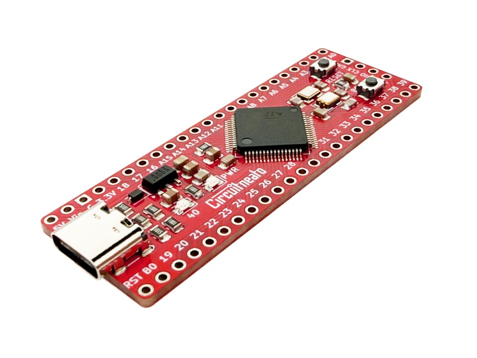
The first 4 pins on the top left are the power pins, which include 5V from the USB port, the regulator input, ground, and the 3.3V regulator output. The first 2 on the bottom left are the reset and bootloader pins, and the rest (besides the 4 pin SWD header on the right) are GPIO pins.
The reset button is marked “RESET” in silkscreen, and the bootloader button is marked “BOOT”. The bootloader or “boot” button will always need to be used when uploading through the USB port. The LED_BUILTIN LED is marked with “40” (because it is connected to pin 40) and the power indicator LED is marked with “PWR”.
On the back of the board are two solder jumpers. One is labelled “LEDs” and will disable both LEDs if cut. The other is labelled “BOOT”, which if you bridge the pads with solder, will connect the boot pin to 3.3V, giving the same effect as the boot button being constantly pressed.
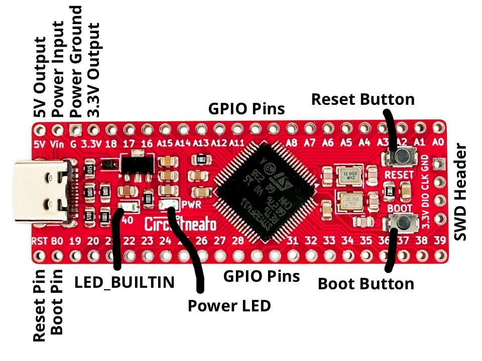
- 5V Output is connected to the 5V bus from the USB-C port, which can be used to power 5V devices, or as a reference voltage for logic level converters. Remember that the logic voltage of the rest of the board is 3.3V, and is in most cases not compatible with 5V logic devices.
- Power Input can be used with an external power source like a battery or a power supply. You can connect up to 24V to this pin, which will be regulated down to 3.3V through the voltage regulator. This pin is also connected to the 5V from the USB port, and has an auto power select diode which allows you to have both sources connected at the same time. The regulator has over-current and thermal protection, and can output up to 500mA to the
3.3Vpin. When powering the board through theVinpin, it is better to use a lower voltage closer to the minimum of 3.8V, as these types of linear regulators turn the extra power into heat. If you are using 24V, you will not be able to draw 500mA before the regulator overheats (without an extra heatsink). - Power Ground is the common ground bus between everything on the board. If you are powering the board or connecting a device to it, you will likely need to connect this pin.
- 3.3V Output is connected to the 3.3V power bus on the whole board and can be used to power small devices like small motors, sensors, and LEDs. It is also the output from the voltage regulator. The
3.3Vpin can also be used as a power input ONLY if your supply is a regulated 3.3V. You can pull up to 500mA from this pin when powering through the USB port or theVinpin. - GPIO Pins Are the input and output pins on the board. There are 40 of them which can all be used as either inputs or outputs. All of the pins can output a PWM signal besides specific pins marked on the bottom of the board. (A0, A1, A2, A3, A8, A12, A13, 17, 29, 30, 31, 32). All of the pins with “A” connect to an ADC channel, and can therefore work as analog inputs which means you can read an analog signal from them, not just a digital signal.
- SWD Header is for programming and debugging the microcontroller with a SWD programmer. For normal use you can program through the USB-C port.
Below is the pinout diagram of the board. Key things to look out for are where the analog pins are, where the solely digital pins are, where the PWM pins are, and where peripheral pins like UART, I2C and SPI are.
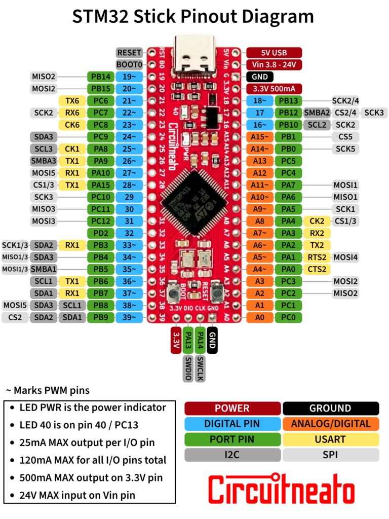
Each GPIO pin can only supply up to 25mA safely, which means you cannot run high power devices (like any motor) directly off of them. But for example, connecting a small LED to a pin directly is okay. There is also a 120mA max output for all of the pins combined, so as an example a limit could be 20mA from 6 I/O pins at the same time. If you need to control high power devices, you can do so by using a MOSFET to supply the device with another power source like the 3.3V from the 3.3V pin, or a higher power external power supply.
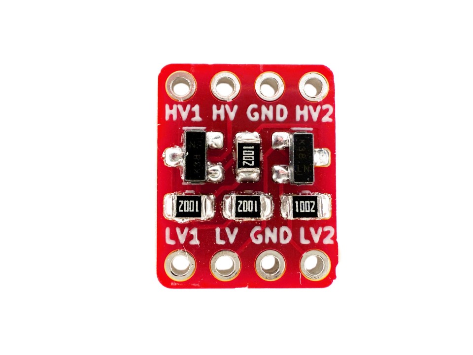
Because this board uses 3.3V logic, connecting 5V devices to the I/O pins is not always safe. In case you need the ability to have 5V outputs or have the all of the pins work as 5V digital inputs, you can use a bidirectional logic level converter like this one to convert those signals from 3.3V to 5V and back.
You can use the 5V pin as a 5V reference along with the 3.3V from the 3.3V pin for hooking up logic level converters. All of the pins can support 5V inputs besides pins A0 and B5. But, 5V tolerant inputs should not have internal pull-up or pull-down resistors enabled, or be used as analog inputs. See the STM32F411RET6 Datasheet for more information.
Setup For Arduino IDE
To program the STM32 Stick in the Arduino IDE, we will need to install a boards package for it and the STM32 Cube Programmer software. Also make sure you have the latest version of the Arduino IDE installed. If you don’t have the Arduino IDE already, you can get it here.
You can install the latest STM32 Cube Programmer software here. It is a tool for programming STM32 products, and you can also use it on its own. Make sure you download it to the default directory, as you wont be able to upload code using the Arduino IDE otherwise.
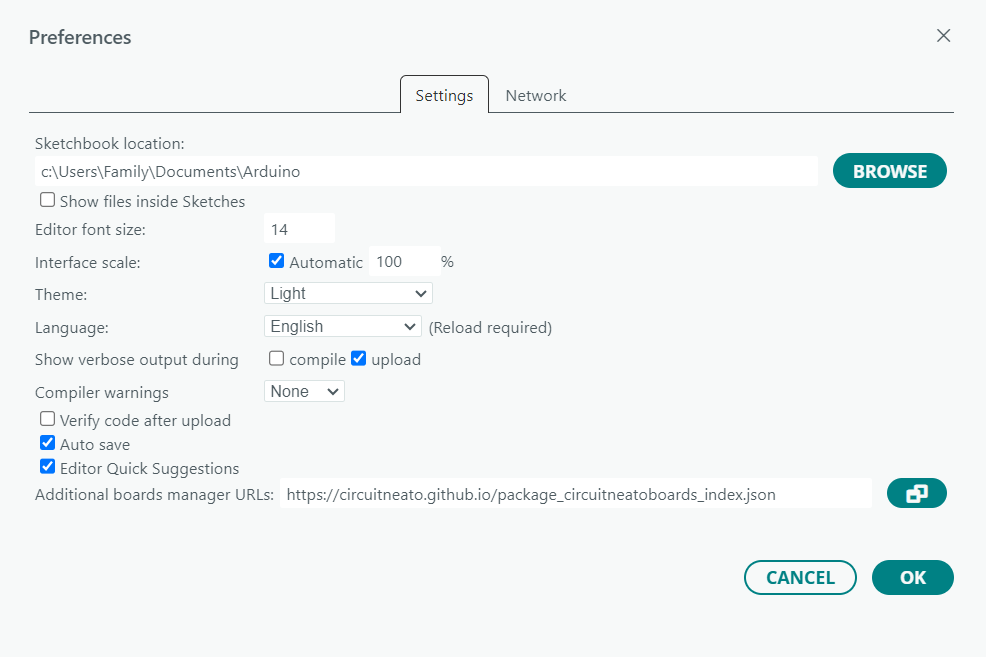
To install the boards package, go to File > Preferences then next to “Additional boards manager URL’s” enter this: https://circuitneato.github.io/package_circuitneatoboards_index.json (making sure it is on a new line if necessary). This will download the needed board definitions in the Arduino IDE.
Now go to Tools > Board > Boards Manager or click the board manager button found at the left side of the IDE screen. Then search for “Circuitneato ARM Boards” and click the install button for “Circuitneato ARM Boards” by Circuitneato Electronics.
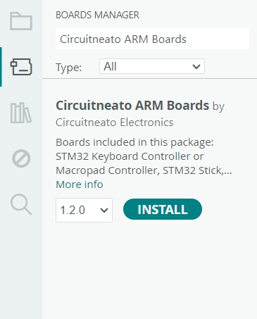
After it finishes installing, go into Tools > Board > Circuitneato ARM Boards and select the STM32 Stick option.
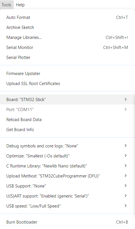
The Upload Method option can be left as default (STM32CubeProgrammer (DFU)), and the USB Support option can be kept set as None, or set to HID to be able to use the board as a keyboard or mouse.
Programming Within the Arduino IDE
You can write code for the STM32 Stick like you would for any other Arduino board. For example, you can use digitalWrite(); and digitalRead(); to write either a high or low signal to any of the pins, or read a high/low signal from them.
You can also use analogWrite(); and analogRead(); to output a PWM signal on the PWM capable pins, or read an analog signal on the analog pins.
pinMode(); can be used to set a pin as an output, input, or an input with its internal pull-up or pull-down resistors enabled pinMode(A0, INPUT_PULLUP); or pinMode(A0, INPUT_PULLDOWN);. And because the microcontroller has native USB, you can also use Arduino libraries like Keyboard and Mouse with it.
Below is a simple blink sketch that will drive pin 40 (which is connected to the LED_BUILTIN LED) high and low every second.
void setup() {
  pinMode(40, OUTPUT);    // set pin 40 as an output
}

void loop() {
  digitalWrite(40, HIGH); // drive pin 40 high (3.3V)
  delay(1000);
  digitalWrite(40, LOW);  // drive pin 40 low (0V)
  delay(1000);
}
Uploading
To upload this code to the STM32 Stick, start by connecting a USB-C cable from the board to your computer. Then double check the board settings are still the same from what we set up at the start of this tutorial. Now hold down the boot button on the board, press the reset button for a short period, and then let go of the boot button. This sets the microcontroller into bootloader mode, and code can now be uploaded. An alternate option is holding down the boot button, plugging in the board, then letting go.
The board wont show as connected in the Arduino IDE like other classic Arduino boards do, which is okay. After pressing the upload button, compiling may take around 20 seconds or more, and after that the code should upload successfully. You will need to put the device in bootloader mode every time before you upload.
If you get an error like this: STM32_Programmer.sh/STM32_Programmer_CLI.exe not found. make sure STM32CubeProgrammer is installed, and if it is, uninstall it and install it again, making sure to set it up with the default settings and file locations. More information can be found here.
Leave a Reply