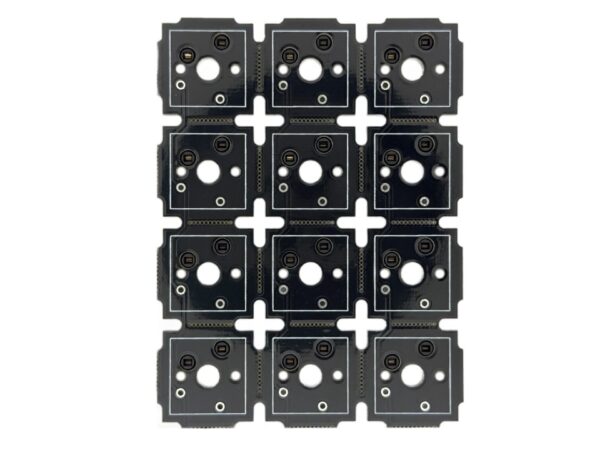
The Customizable Size Macropad PCB is a customizable sized Macropad/keyboard PCB mainly for handwired macropads. Any size can be ordered up to a 5×5 (5 Rows, 5 Columns), and it is assembled with nearly everything you need to make a custom macropad.
Layout
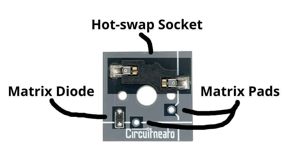
Each square in the PCB has a Gateron hot-swap socket (Hot-swap Socket) for quick inserting and swapping of your mechanical switches. There are drilled holes to allow for 3 pin and 5 pin MX style switches. For the keyboard matrix, there are diodes facing down to each row (Matrix Diode), and silkscreen marking where each trace is for ease of use. There are two THT pads (Matrix Pads) in each square so you can wire the matrix to your controller.
How to Wire
Things to know before starting:
We will use the words “keyboard matrix” or “matrix” a lot in this tutorial so you should know what it means if you don’t already. If you don’t know, a keyboard matrix is a grid of switches electrically connected by rows and columns, allowing an easy way to control a large grid of keyboard switches with the microcontroller. Without a keyboard matrix, each key would have to be directly connected to the microcontroller taking up two I/O pins thus not allowing for large amounts of keys like a full keyboard.
Tools/materials needed:
- Soldering iron
- 20-28 gauge wire
- Leaded or lead-free solder wire (1mm diameter will work)
- Wire cutters or scissors
Optional tools/materials:
- Wire strippers
- Flux paste
Warning: Soldering is required for this project, always solder in a well ventilated area.
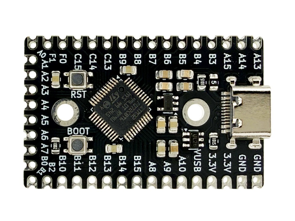
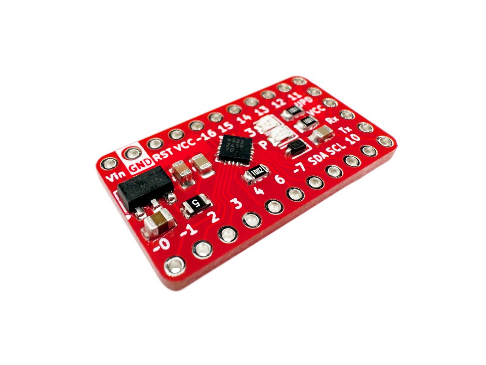
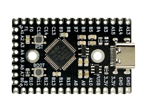
To start, you will need to find a controller board with enough pins to support your keyboard matrix. As an example, If you have a 3 column by 4 row matrix, you will need 7 I/O pins on your controller. Some recommendations for controllers are Pro-micro development Boards with the ATmega32u4 or our STM32 Keyboard Controller. Either will work the same way and are both as easy to use as one another. But, the STM32 chip on our controller has more storage and more I/O pins than the ATmega32u4, which is why it is generally considered a better option in the keyboard building community.
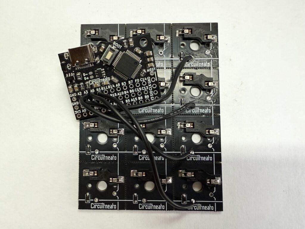
After you have selected your controller board, you can start planning out the matrix. Each row and column needs to be connected to a pin on the controller. Rows are marked with the horizontal silkscreen lines, and columns are marked with the vertical silkscreen lines. These lines will cross over each THT pad in that row/column. Every pad they cross over is electrically connected together. This means you can pick any of the THT pads on the line to solder to. In our case, we will solder a wire to the first pad on the very first row. This will be row 0. We can then solder this to an available I/O pin on our controller.

We can now do the same thing with the rest of our rows.
After all of our rows are soldered to the controller, we can start with our columns, the same way we did with the rows.

This is the end of this tutorial. You are now done soldering the PCB to your controller. You can read our STM32 Keyboard Controller tutorial for example code using Arduino libraries, and for QMK (Quantum Mechanical Keyboard). If you don’t know, QMK is open-source firmware made for keyboards. And it has plenty of documentation here.