Introduction
The NEMA17 Onboard Stepper Motor Driver is a very handy controller for NEMA17 motors. What makes it so handy is that it sticks to the back of any NEMA17 motor, and can be directly connected with a stepper motor cable. The driver is based off the popular DRV8825 Stepper Motor Controller IC which has a large voltage rating and high current rating.
Layout
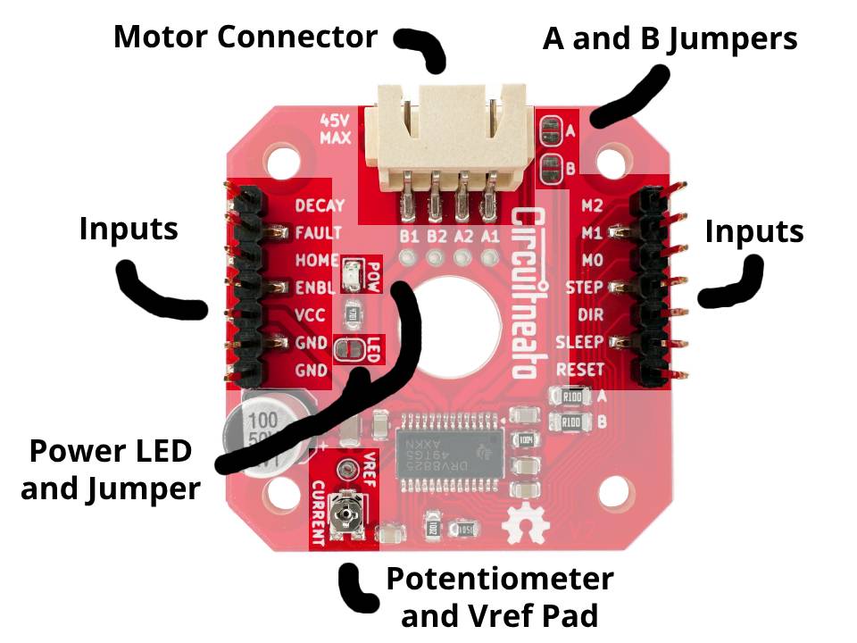
The driver board has two rows of vertical male header pins that are connected to the various inputs, including VCC and GND. The white connector is a 4 pin, 2.5mm pitch, XH connector that fits standard stepper motor cables (MPN: S4B-XH-SM4-TB(LF)(SN)). The POW LED indicates if the board is powered, and can be disabled by cutting the LED jumper. The A and B jumpers are for bypassing the current sense resistors (which a resistor can also be soldered on top of them). There is a current limiting potentiometer with a VREF pad to better set the current limit. And there are also 4 mounting holes around the edges of the board, but it’s more than likely the screws in your stepper motor wont be long enough for you to use them.
Features
This stepper motor driver has a supply voltage range from 8.2V to 45V, and a max current per coil of 2.2A. The continuous current without a heatsink is about 1.5A, and a little higher when attached to a stepper motor. The board also has large power supply filtering capacitors on the board for better motor performance. More features of just the DRV8825 include:
- 3.3V and 5V logic levels
- Adjustable max current control
- Multiple step resolutions including, full-step, half-step, 1/4-step, 1/8-step, 1/16-step, and 1/32-step
- Slow, mixed, and fast decay modes
- Step and direction control interface
- Low current sleep mode
- Overcurrent protection
- Thermal shutdown
- Undervoltage lockout
Assembly
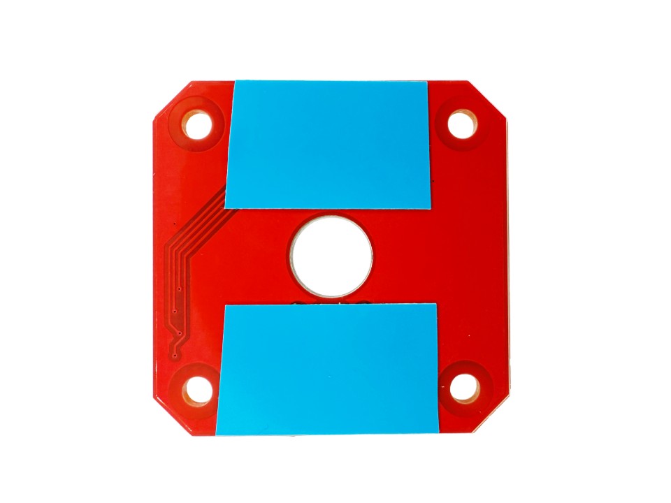
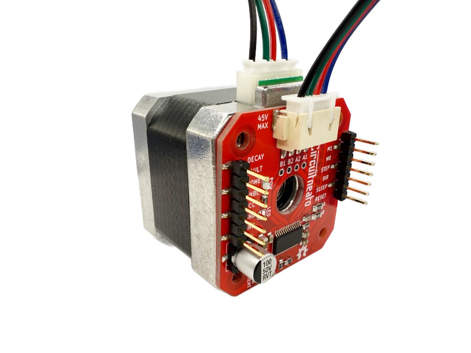
As stated earlier, the screws in the back of your stepper motor should line up with the holes in the driver board, but are likely not long enough for the extra gap. So instead, each driver board comes with 2 pieces of thermal double sided tape on the back of the board which you can use to stick your driver to the back of your motor. The tape also minorly helps with cooling the DRV8825 chip, allowing the stepper motor to work as a heatsink.
Setting the Current Limit
The potentiometer on the driver board is used for setting the max current limit of the DRV8825. The main reason this is done is to allow the stepper motor to all run at higher voltages, without the current draw getting higher too. This allows higher step rates for the motor which you couldn’t get if you were stuck with using lower voltages.
Setting the current limit only needs to be done once per motor driver, unless you change the stepper motor you are using with it. To start, get a multimeter (to measure the VREF voltage), a 3.3V – 5V power supply (like the 5V output on an Arduino UNO or other development boards), a 8.2V – 45V power supply for the driver supply power (we will use 12V), and some jumper wires.
First make sure your motor is disconnected from the motor driver, then connect the 5V supply to pins SLEEP and RESET, and it’s ground to one of the GND pins. Next connect the 12V power supply to the other GND pin and the VCC pin.
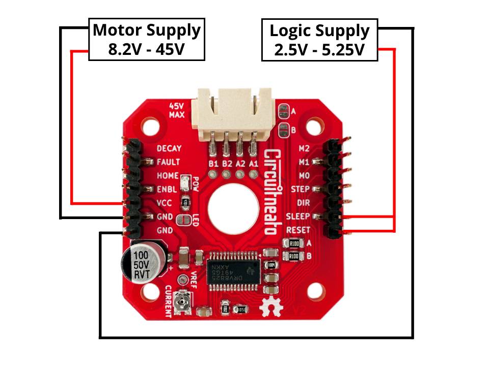
Turn on both power sources and the red power LED should turn on. Now connect one of your multimeter probes to ground, and the other probe to either the center of the potentiometer or the VREF pad. By turning the potentiometer, the VREF voltage will change.
To know what voltage we need to change the VREF voltage to, you can follow this formula:
VREF = Current Limit / 2
The current limit on our NEMA17 stepper motor is 1.5A, which 1.5 divided by 2 is 0.75. and to be on the safe side, we will go slightly lower with 0.7V. Now we can rotate our potentiometer until we get a reading of 0.7V on our multimeter. If you aren’t getting any reading, make sure there is a common ground between the 8.2V – 45V power supply and the 3.3V – 5V power supply.
Usage Examples
You can control the driver with any development board like an Arduino UNO or a Tineato 3226. But first, lets go over the inputs. One high pulse to the STEP pin advances the motor one microstep in the direction selected by the DIR pin. The RESET and SLEEP pins must be high to allow the driver to operate, as they are pulled low internally. The ENBL pin’s default state already enables the driver so it does not need to be connected to anything. The FAULT pin goes low when any of the DRV8825’s protection circuits get triggered, and it is connected to a pull-up resistor to the SLEEP pin so it will stay high. The HOME pin is broken out which goes low when the driver is at the beginning of the step table. It does not need to be connected. The DECAY pin is left open and disconnected by default for mixed decay mode, but can be driven low for slow decay mode, and high for fast decay mode.
M0, M1, and M2 are used for setting the step size. Most stepper motors have a step size rating like 1.8° or 200 steps per revolution, which would be full steps. The DRV8825 is able to run stepper motors at finer step resolutions known as microstepping. For example, driving a 200 steps per revolution motor in half-step mode will allow for 400 microsteps per revolution. Below is a chart on how to set your step modes. Note that M0, M1, and M2 have internal pull-down resistors, which allows for leaving those pins disconnected for full-step mode.
| M0 | M1 | M2 | Microstep Mode |
|---|---|---|---|
| Low | Low | Low | Full-step |
| High | Low | Low | 1/2-step |
| Low | High | Low | 1/4-step |
| High | High | Low | 1/8-step |
| Low | Low | High | 1/16-step |
| High | Low | High | 1/32-step |
| Low | High | High | 1/32-step |
| High | High | High | 1/32-step |
Full-Step Mode with AccelStepper Library
We will use the handy AccelStepper library for easily controlling our stepper motors. To install it, go to Tools > Manage libraries… then search for “AccelStepper”. Click install for the latest version and you are ready to go!

Below will be our connections to our stepper motor driver:
VCCto 8.2V – 45VGNDto power supply groundGNDto development board groundDIRto pin 2STEPto pin 3SLEEPto 3.3V – 5VRESETto 3.3V – 5VM0to pin 4M1to pin 5M2to pin 6
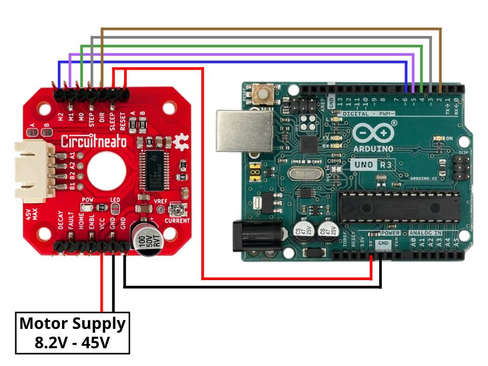
Now before uploading any code or powering either of the boards, plug the stepper motor driver into your stepper motor. If you don’t have a motor connected to the output while controlling the driver, it can damage the DRV8825 chip. If you ever need to change the wiring or disconnect the motor, make sure the driver is disconnected from power.
The code below continuously rotates the stepper motor at 200 steps per second on full-step mode. You can upload it to your development board and power on the driver to watch the motor spin!
#include <AccelStepper.h>

// define pin connections
#define dirPin 2
#define stepPin 3

#define motorInterfaceType 1

AccelStepper stepper(motorInterfaceType, stepPin, dirPin);

void setup() {
  // set max speed to 1000 steps per second
  stepper.setMaxSpeed(1000);

  // set speed to 200 steps per second
  stepper.setSpeed(200);
}

void loop() {
  stepper.runSpeed();
}
Note: If your stepper motor seems jittery and/or is very loud, try slightly lowering the current limit using the potentiometer.
1/32-Step Mode with AccelStepper Library
Now we will change our step mode from full-step to 1/32-step. We do this by setting the mode pins high or low with accordance to the chart further above. For 1/32-step mode there are multiple options of high/low configurations, but the easiest is just driving M0, M1, and M2 all high. We will use the same code as before, but drive pins 4, 5, and 6 high. As an example, if we wanted to use the 1/8-step mode, we would set pin 4 high, pin 5 high, and pin 6 low. We will also make the steps per second speed faster, as now we 32 steps per every 1 step we had before.
#include <AccelStepper.h>

// define pin connections
#define dirPin 2
#define stepPin 3

#define motorInterfaceType 1

AccelStepper stepper(motorInterfaceType, stepPin, dirPin);

void setup() {
  // set max speed to 1000 steps per second
  stepper.setMaxSpeed(1000);

  // set speed to 200 steps per second
  stepper.setSpeed(800);

  // make mode pins outputs
  pinMode(4, OUTPUT);
  pinMode(5, OUTPUT);
  pinMode(6, OUTPUT);

  // drive them all high
  digitalWrite(4, HIGH);
  digitalWrite(5, HIGH);
  digitalWrite(6, HIGH);
}

void loop() {
  stepper.runSpeed();
}
There is a limit to how fast you can turn the stepper motor, especially at finer microstepping resolutions. An Arduino UNO can only handle up to about 4000 steps per second because it has a clock speed of only 16MHz. So if you wanted to spin a 200 step stepper motor at 1 revolution per second with 1/32-step microstepping, the UNO would be trying to send 6400 step pules each second, which is well over the 4K limit. But you can do this, and run even faster step rates if you use a faster microcontroller like an ESP32 which can do up to about 40K steps per second.



Leave a Reply
You must be logged in to post a comment.