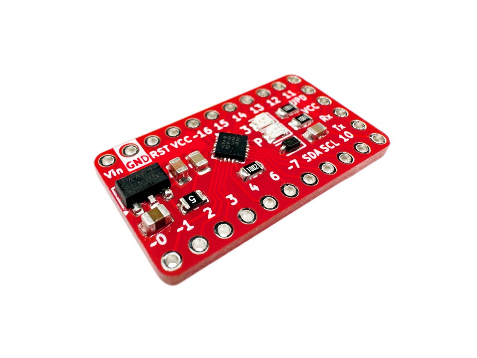
This is a general tutorial for how to use the STM32 Keyboard Controller, but it also covers how to use it with QMK. See the “Firmware Overview” section for how you can use the controller with the Arduino IDE. The STM32 Keyboard Controller is designed for making handwired keyboards but can also be used for macropads.
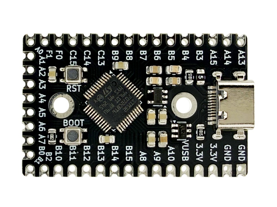
It’s main features are 35 I/O pins for over “100%” keyboards, 128 Kbytes of flash memory for more features, shortcuts, and macros, a mid-mount USB-C port for slim designs, a 2 M2.5 holes for easy mounting, silkscreen identifiers for each pin, buttons for resetting and entering bootloader mode, and more! The board also has no LEDs so no unwanted light will shine through your build. We also sell a similar STM32 Macropad Controller for smaller keyboards and macropads.
Layout
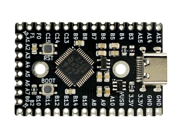
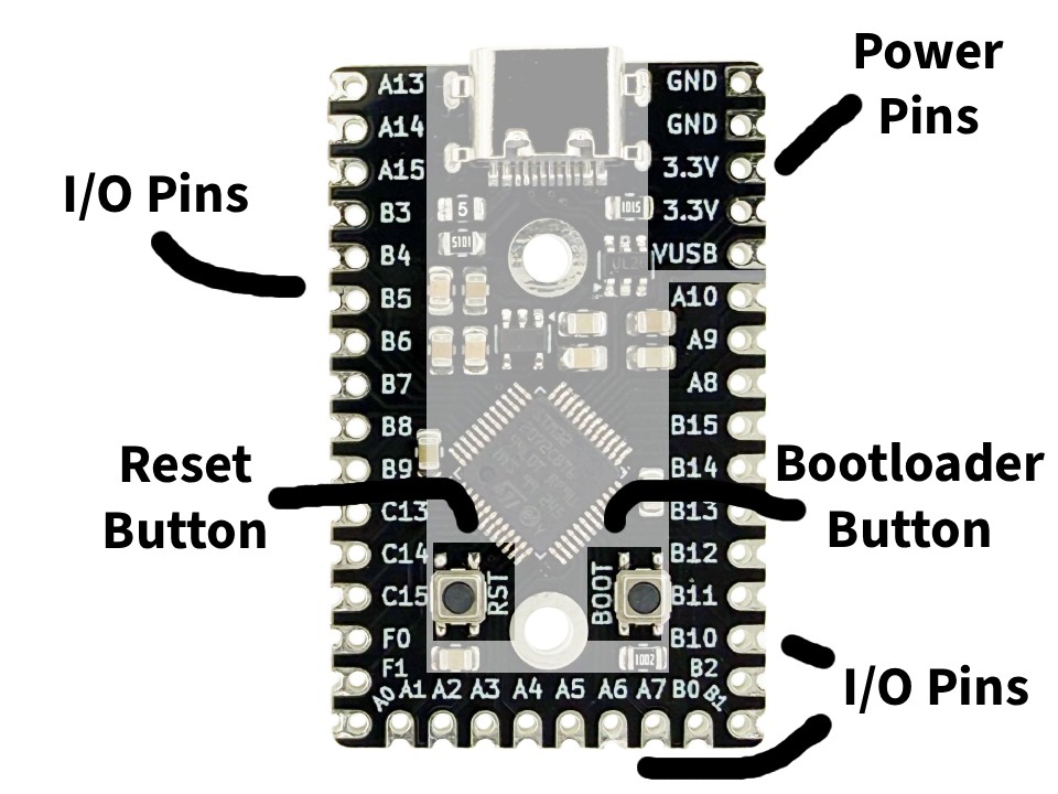
The board has all of the I/O pins that can be used for a keyboard matrix along three sides of the board. There are 5 power pins including 2 pins for GND, 2 for 3.3V, and a VUSB pin. The VUSB pin is polyfuse protected 5V from the USB-C port, which often wont be needed but can be used for specific devices that require 5V power. All of these pins along the three sides of the board are castellated pads, which allow you to solder to them normally though the hole, or solder them to a PCB with the correct footprint. You can find the footprint and schematic symbol in the documentation section below.
The bootloader button is used for programming the controller, and is marked with “BOOT” silkscreen text. It may also be used along with the reset button which is marked with “RST” silkscreen text. There are also 2 pads on the backside of the board for D- and D+ from the USB-C port for debugging if needed. The two mounting holes are located near the USB-C port and near the reset and bootloader buttons. Their silver pads are not electrically connected to anything.
Wiring
Wiring a keyboard matrix on the STM32 Keyboard Controller is easy. If you don’t know, a keyboard matrix is a grid of switches electrically connected by rows and columns, allowing an easy way to control a large grid of them with a microcontroller. Without a keyboard matrix, each key would have to be directly connected to two pins, thus not allowing for large amounts of keys like on a full keyboard. In this tutorial we will use our Customizable Size Macropad/Keyboard PCB as it already places each mechanical switch/key in a keyboard matrix, and included the necessary diodes. We will also go over how to make these matrixes by hand.
Tools/materials needed:
- Soldering iron
- 20-28 AWG wire (22 AWG recommended)
- Leaded or lead-free solder wire (1mm diameter will work)
- Wire cutters or scissors
Optional tools/materials:
- Wire strippers
- Flux paste
Remember to always solder in a well ventilated area.
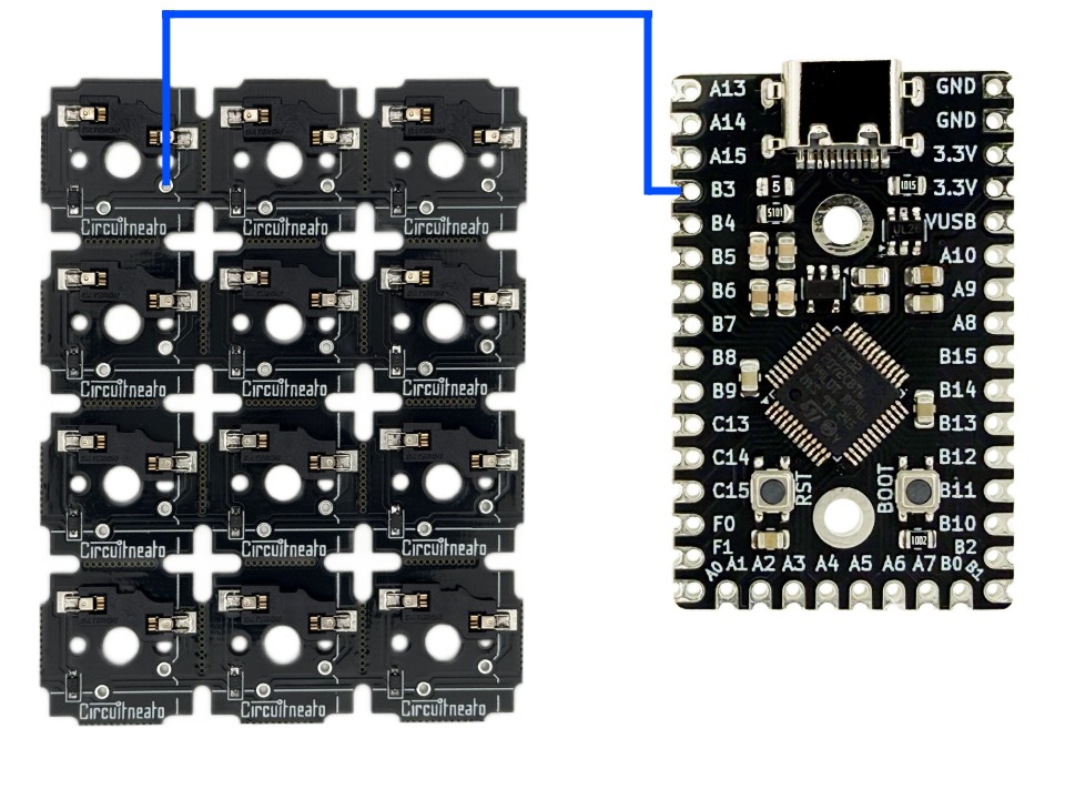
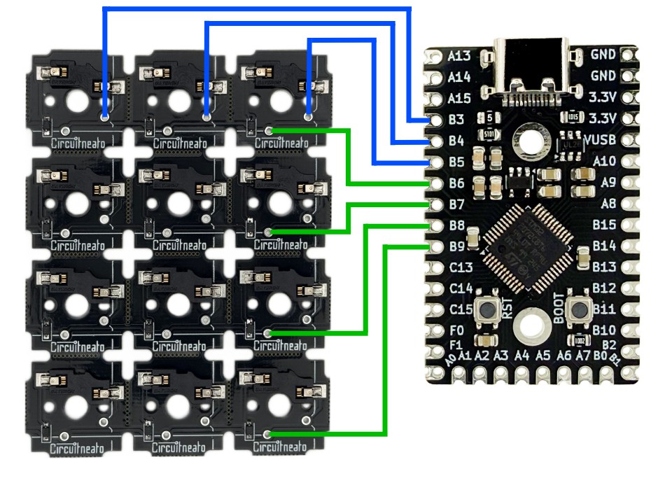
Start by cutting a length of wire, and stripping about 1/8″ of the insulation off one end. Then starting on the controller, solder the end of that wire onto one of the I/O pins, for this we will use B3.
Now cut the other end of the wire to its final length, depending on the design on your keyboard/macropad this may need to be several inches or just a couple. Starting on the back side of the keyboard PCB (the side with the diodes and hot swap sockets), strip the other end of the wire and solder it to one of the column pads on the left most column. Which column pad you solder to does not matter, as long as it is in the right column. The vertical silkscreen lines show the columns, and the horizontal silkscreen lines show the rows.
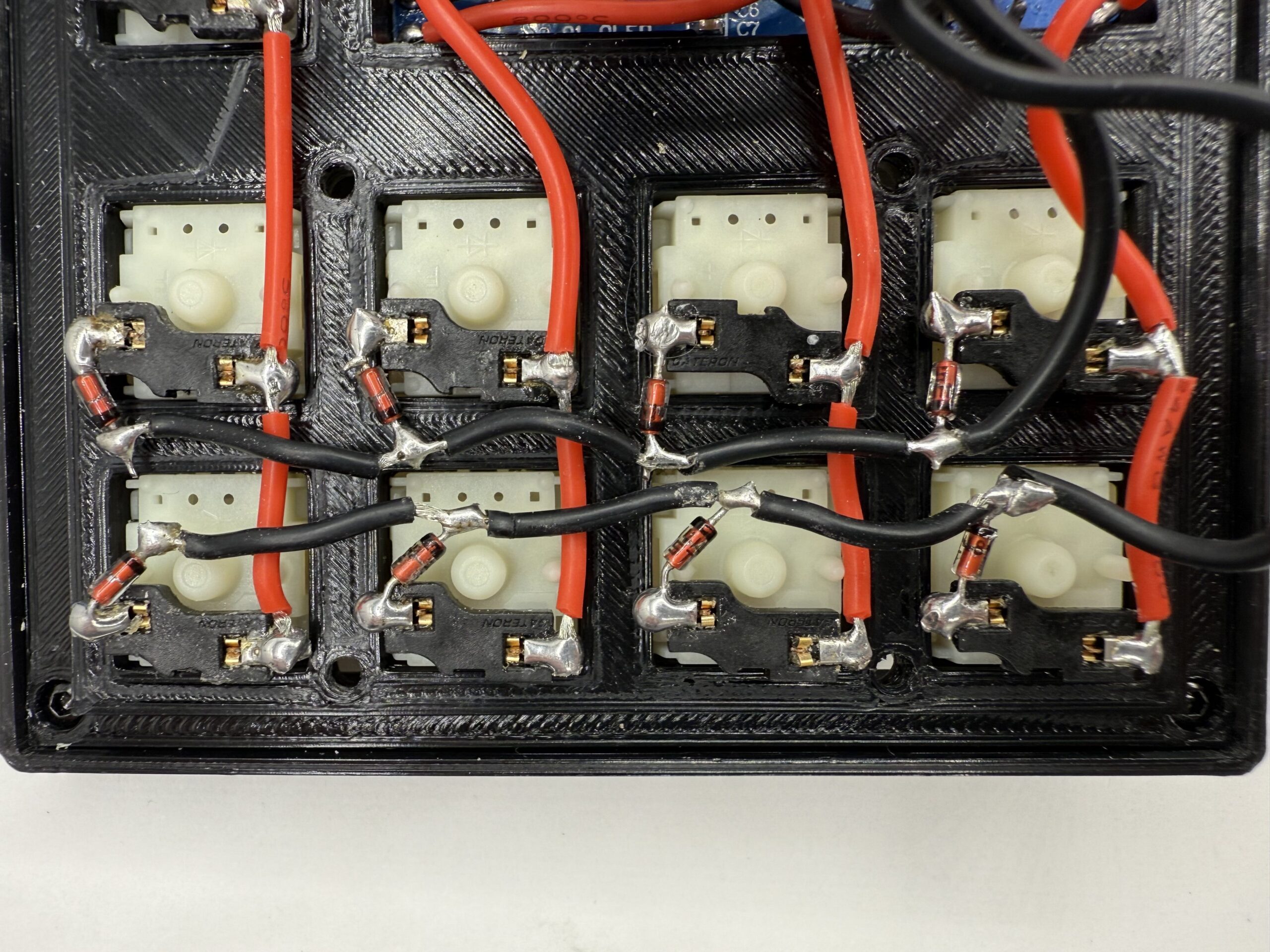
If you just have stand-alone mechanical switches, you can solder them together like in the image below, where each key is connected to a row and column chain. There will also need to be a diode (1N4148 works well) for each switch facing towards it’s row. The red wires are the columns, and the black wires are the rows. The diodes are red and have a black line to show which way it is facing.
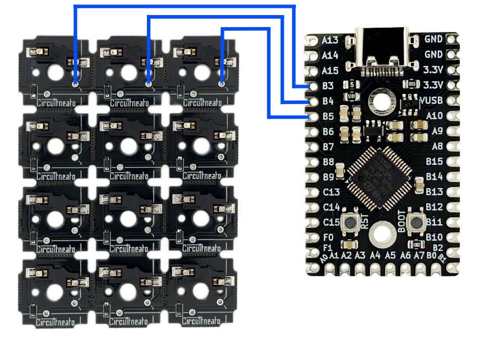
You can repeat the steps above, soldering the next pin to the next column and so on. For this macropad, I soldered the middle column to B4, and the right most column to B5.
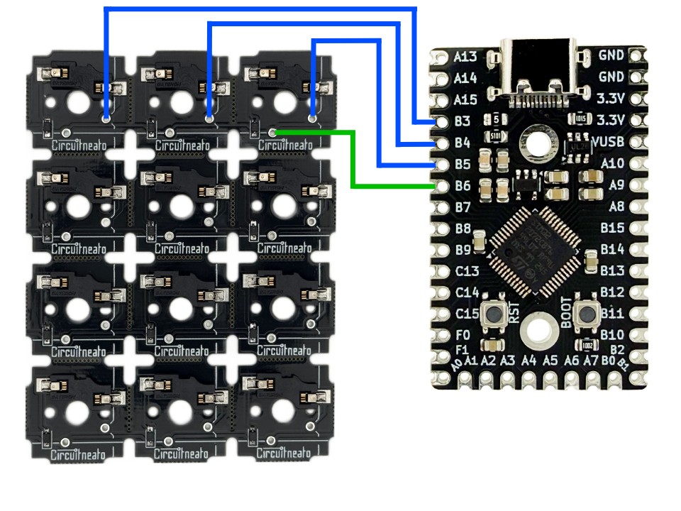
Once all of the columns have been connected, you can move on to the rows. Following the same steps as you did with the columns, you can start with the top row and choose one of the pads to solder to. I connected this row to B6.
Repeat these steps again with the rest of the rows. I soldered the 2nd row from the top to B7, the 2nd row from the bottom to B8, and the bottom row to B9. That is all the wiring required for a simple keyboard matrix.
Firmware Overview
This tutorial will go over making keyboard firmware with QMK (Quantum Mechanical Keyboard). If you don’t know, QMK is open-source firmware made for keyboards. And it has plenty of documentation here. If you want to program your keyboard controller with the Arduino IDE and Arduino libraries, you can switch to this tutorial now, but I recommend using QMK.
Writing Firmware with QMK
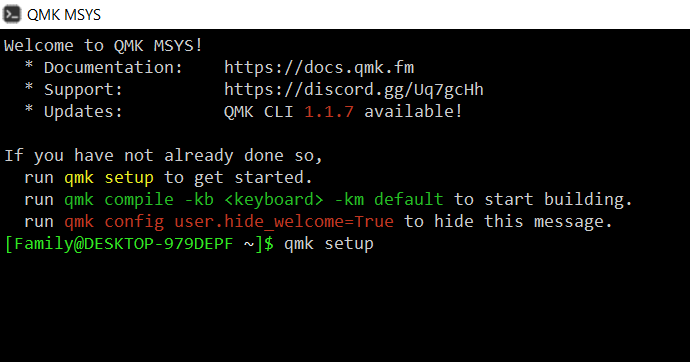
Making keyboards and macropads is easy using QMK. But you will need to download a few things first. The first thing you need to download is QMK MSYS, which is a CLI (command line interface) that we will use to compile our scripts. You can download the latest release on GitHub (Click on the latest release version and then download the .exe file).
A text editor will also be needed to write your scripts. You may be able to use the default text app on your system, as long as it saves in plain text files. We and QMK developers recommend using VScode or Sublime. In this tutorial we will write our scripts in the VScode editor.
You may also want to download QMK Toolbox (optional), It is a GUI (Graphical User Interface) program that we will use to flash our boards. You can also do this with the QMK MSYS if you want to stay simplistic.
After all of this is done, we can set up QMK in QMK MSYS. Open up QMK MSYS that you downloaded in the last step and after it loads, type and enter the command qmk setup and enter y for all of the prompts it gives you.
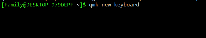
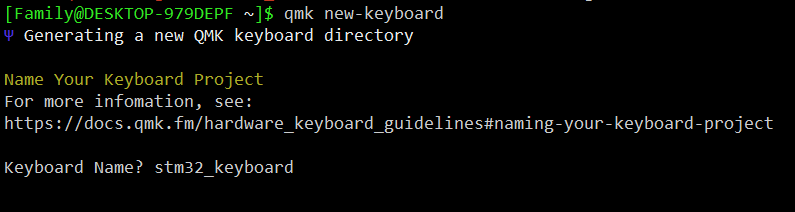
Once QMK has set up, we can create our first keyboard. You can create your keyboard by entering the command qmk new-keyboard into QMK MSYS.
It will then ask you what you would like to name your keyboard. Make sure to only use lowercase a-z, numbers 0-9, underscores _, and no spaces!
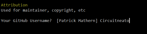
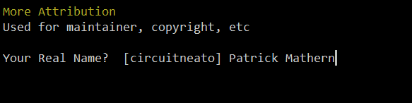
Now it will prompt you to enter your GitHub username followed by your real name. If you don’t have a GitHub username, you can just enter your name or something else. When it asks for your real name you can also put it or something else.
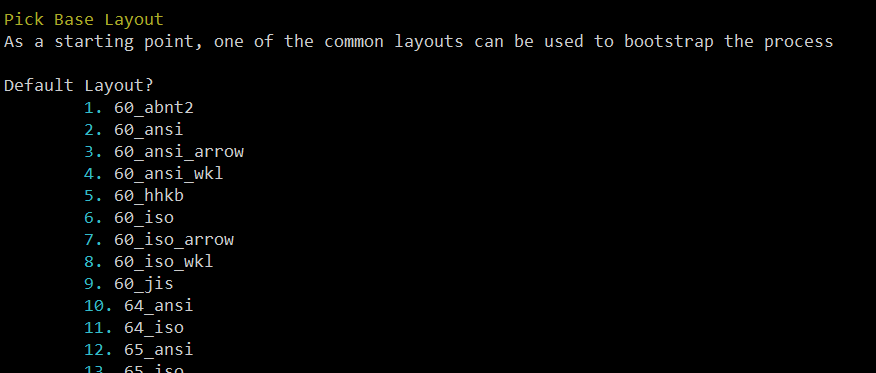
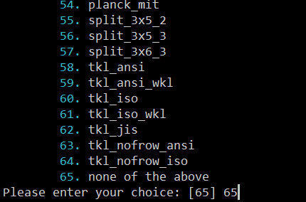
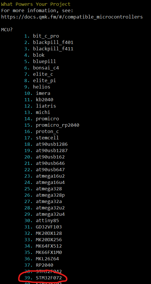
Next you will get a list of already made keyboard layouts which we will not use, and instead make a custom one using the last option. In this version it is #65, but it may be different in future versions.
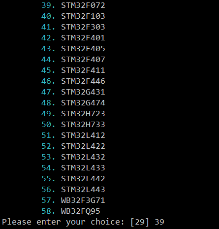
You will then be asked what MCU your board uses, in our case the STM32F072. In this version it is #39.
Finally you should receive a confirmation message like the one below! Make note of the “Project Location” where your new keyboard files will be located on your system for editing.
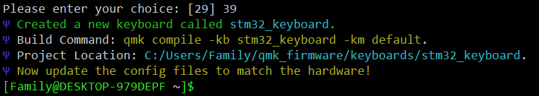
In your device’s files, locate the folder shown next to “Project Location”, and open keyboard.json in your text editor. In our case, that file location isC:/Users/Family/qmk_firmware/keyboards/stm32_keyboard/keyboard.json
Upon entering keyboard.json, the file’s code should look something like this:
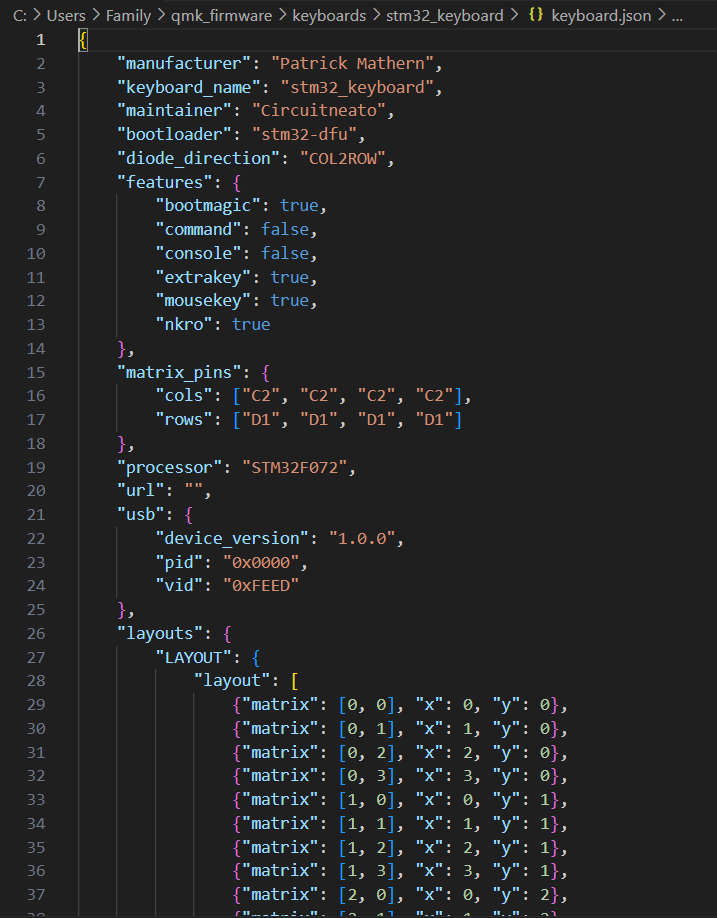
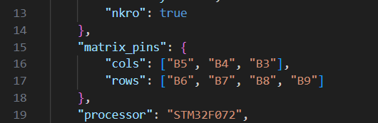
The first thing we need to edit is under "matrix_pins": { and defines what pins on our microcontroller are connected to which columns and which rows. In our main wiring example above, our columns (starting from the left if looking from the top side of the keyboard, not the wiring side) are connected to pins B5, B4, and B3. And our rows (starting from the top if looking from the top side of the keyboard) are connected to pins B6, B7, B8, and B9. We can input these values as shown below.
"matrix_pins": {
    "cols": ["B5", "B4", "B3"],
    "rows": ["B6", "B7", "B8", "B9"]
},
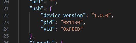
Next we can scroll down in our code to the line that says "usb": { This is where we can enter our device version, product id, and vendor id. Our product id and vendor id are for distinguishing our keyboard from others in the small chance that another peripheral with the same pid and vid are connected. For your hobby use, you can leave them as is, or change them to any number you’d like. For our tutorial keyboard, we will leave vid the same, and change pid to 0x1130.
"usb": {
    "device_version": "1.0.0",
    "pid": "0x1130",
    "vid": "0xFEED"
},
Finally we can scroll down once more to the line that says "layouts": {. This is where we define the key makeup of our keyboard, or in other words, where each key is located on an imaginary grid. It can be confusing to look at, but if explained well it is easy to understand.
In this layout we need to follow along with how many columns and rows we inputted values for in “matrix_pins”, we need to make sure to add 3 columns and 4 rows here to correlate with the 3 column inputs and 4 row inputs. Now lets breakdown one of these lines to better understand it.{"matrix": [0, 0], "x": 0, "y": 0}
The first part is "matrix": [0, 0] which defines the row and column respectively. 0 being the first row/column, 1 being the second row/column, etc. The second part of this line is "x": 0, "y": 0
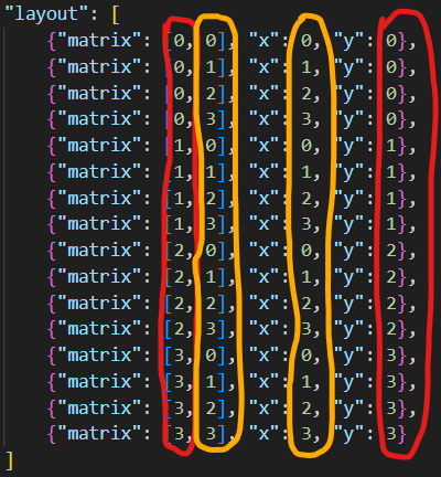
Below are the values that we will use for our 4 row by 3 column keyboard:
"layout": [
    {"matrix": [0, 0], "x": 0, "y": 0},
    {"matrix": [0, 1], "x": 1, "y": 0},
    {"matrix": [0, 2], "x": 2, "y": 0},
    {"matrix": [1, 0], "x": 0, "y": 1},
    {"matrix": [1, 1], "x": 1, "y": 1},
    {"matrix": [1, 2], "x": 2, "y": 1},
    {"matrix": [2, 0], "x": 0, "y": 2},
    {"matrix": [2, 1], "x": 1, "y": 2},
    {"matrix": [2, 2], "x": 2, "y": 2},
    {"matrix": [3, 0], "x": 0, "y": 3},
    {"matrix": [3, 1], "x": 1, "y": 3},
    {"matrix": [3, 2], "x": 2, "y": 3}
]
For row 0, we have columns 0, 1, and 2. For row 1, we have columns 0, 1, and 2. And so on until row 4. This gives us each of our 4 rows and each of our 3 columns to make 12 key “coordinates” on our imaginary grid.
We are done with our keyboard.json file, so we can move to our keymap. To find your keymap, go back to your keyboard’s folder and open keymaps > default > keymap.c then open it in your text editor. The file should look something like this.
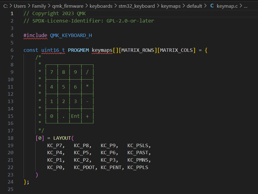
On line 18 under where it says [0] = LAYOUT( is where we will define what each key will do by typing in “keycodes”. The keycodes are all of the letters, numbers, symbols, and modifiers that you can find on a normal keyboard. (modifiers are like the shift and Ctrl keys). You can find a full list of keycodes that QMK supports here. In this tutorial we will focus on the “basic keycodes” on that list.
There are 12 keys on our keyboard, so we need to make sure we also have 12 keycodes in our keymap. The first keycode we type will be for the first key on our keyboard, on row 0 and column 0. This is the top left corner if we have the wiring facing down and keys facing up. We are going to make our keyboard a number pad, so our first keycode will be the number 1. That keycode is KC_1. Most basic keycodes like ones for letters and numbers will start with KC_ and end with the character, in our case, 1. We can type in the rest of our keycodes each followed by a comma as shown below.
[0] = LAYOUT(
    KC_1,        KC_2, KC_3,
    KC_4,        KC_5, KC_6,
    KC_7,        KC_8, KC_9,
    KC_ASTERISK, KC_0, KC_HASH
)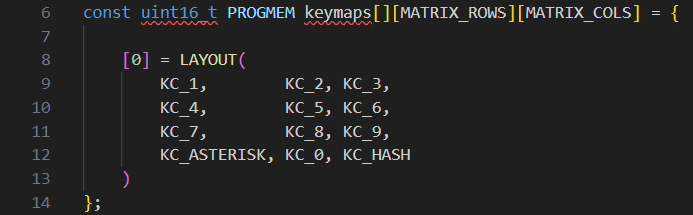
Above are numbers 1-9, then an asterisk *, then number 0, and finally a hash #.
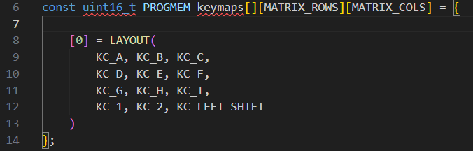
Here is an example with letters, numbers and a shift key so you can use the character’s uppercase versions or symbols. For example shift + 2 makes a @, and shift + a makes an uppercase A
[0] = LAYOUT(
    KC_A, KC_B, KC_C,
    KC_D, KC_E, KC_F,
    KC_G, KC_H, KC_I,
    KC_1, KC_2, KC_LEFT_SHIFT
)
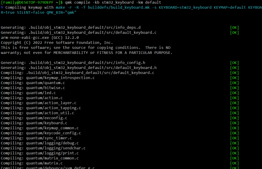
Once you are happy with your keymap, it is time to compile your code using the QMK MSYS. Open the QMK MSYS and once it loads, enter the command qmk compile -kb stm32_keyboard -km default replace the “stm32_keyboard” with whatever you named your keyboard when making it earlier. If you forgot, you can check the keyboard_name line in your keyboard.json file.

After waiting a bit, you should receive an output like the one below.
If you received an output like the one below, you most likely typed your keyboard name wrong in the command, so you can double check that and try again.

After you have successfully compiled your keyboard, open up QMK Toolbox that we downloaded earlier so we can flash our code to our STM32 Keyboard Controller. At the top of QMK Toolbox there is a button labeled “Open”. Click on that button and it should pop up the needed file location on our computer. (This file location is the qmk_firmware directory if it did not open automatically). In this directory you should see a .bin file with the name of your keyboard, in this case, stm32_keyboard_default.bin You should then open this file in QMK Toolbox.

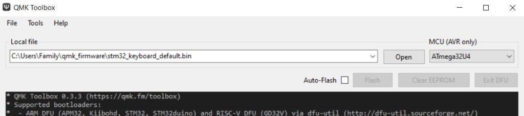
Now click on the box next to “Auto-Flash” to enable it. This is all we should need to configure. You don’t need to worry about choosing the correct MCU in the “MCU (AVR only)” dropdown for our STM32 controller.
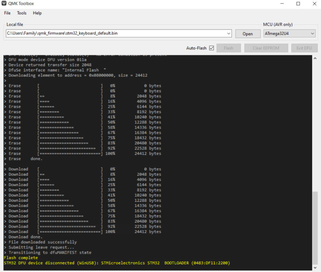
To upload/flash the code, get a USB-C cable and connect your controller to your computer. (Any USB cable will work as long as one side is USB-C). Once connected, enter bootloader mode by holding down the BOOT button and pressing the RST button once, then letting go of the BOOT button. You should see text on the QMK Toolbox output like below. Once the output says “Flash complete” in yellow text, you are done.
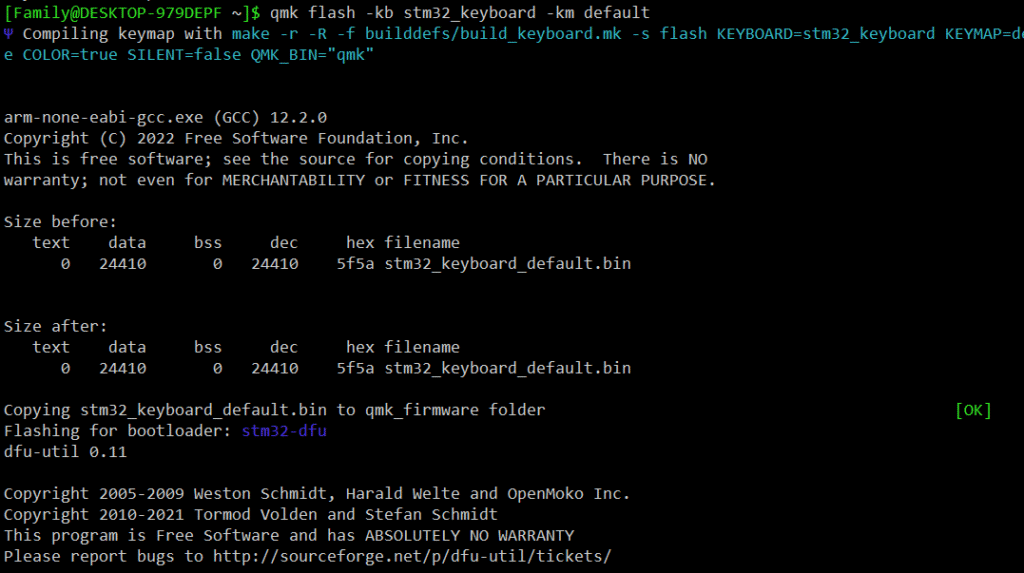
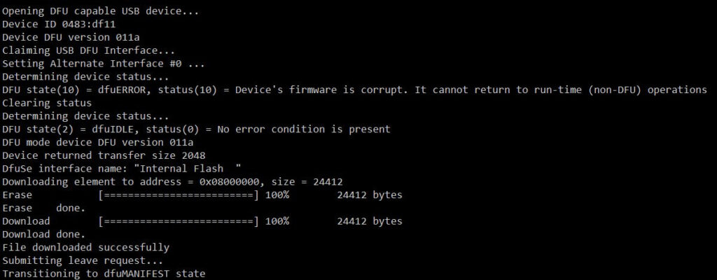
If you can’t flash your keyboard with QMK Toolbox, or would just like to use QMK MSYS instead, follow these directions: Connect the controller to your computer and enter bootloader mode like we did above. Then in QMK MSYS type the command qmk flash -kb stm32_keyboard -km default replacing “stm32_keyboard” with the name of your keyboard per usual, then press enter. You should receive an output like below. If it gets stuck trying to find a device in bootloader mode, try entering bootloader mode again while it is still checking.
To test to make sure all the keys on your keyboard work, plug your USB-C cable back into your keyboard, and wait for your computer to set up the device if it needs to. Then you can go into a text document and press each key, or you can go to VIA for a free key tester. Simply press each key while you have your keyboard connected and the keys that you programmed it with will light up and make a noise on the tester website (VIA).
If you want to make any new changes to the firmware, you can edit the files then re-compile and flash the new code to the controller just the same way as before. Our keyboard.json file from earlier included this line of code "bootmagic", true, that allows us to use the first key on our keyboard (row 0, column 0) in place of the BOOT button if you can no longer reach it on your finished keyboard. You can use it the same way as the BOOT button to re-flash the controller, but by holding it down then plugging in the USB-C cable.
If you have any problems flashing to the controller, try doing it both ways shown here, or compiling the code again. If you are still having problems with flashing or anything else, please check the QMK docs as there is a lot of information well organized there, or leave a comment below.