Make sure you have read our tutorial on the basics of the STM32 Keyboard Controller, for the layout, wiring, and more. We recommend using QMK firmware with your Keyboard Controller as it is a lot easier to use, but if you are used to programming in the Arduino IDE, or just don’t want to download many extra things, you can use the IDE with code libraries.
Setup for Arduino IDE
If you want to program your board with the Arduino IDE, you can follow these steps. Make sure you have the latest version of the Arduino IDE installed. If you don’t have the Arduino IDE already, you can get it here.
Then you need to install the latest STM32 Cube Programmer software. You can find it here. It is a tool for programming STM32 products, and you can use it on its own. Make sure you download it to the default directory, as you wont be able to upload code using the Arduino IDE otherwise.
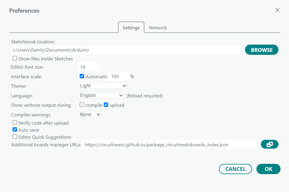
The last thing you need to do is add the Circuitneato ARM Boards board package to the Arduino IDE. Start by going to File > Preferences and in the Additional Boards Manager URLs field, paste this link:
https://circuitneato.github.io/package_circuitneatoboards_index.json
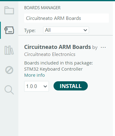
This will download the needed board definitions in the Arduino IDE. Now go to Tools > Board > Boards Manager or click the board manager button found at the left side of the IDE screen. Then search for “Circuitneato ARM Boards” and click the install button for “Circuitneato ARM Boards” by Circuitneato Electronics.
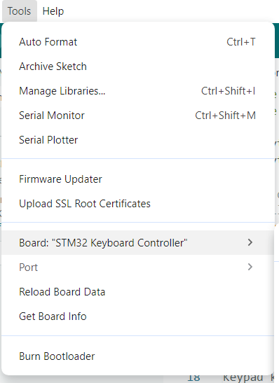
After the package is done installing, we will select the correct board. Go to Tools > Board and select STM32 Keyboard Controller.
Now our IDE is set up with everything we need to program the STM32 Keyboard Controller.
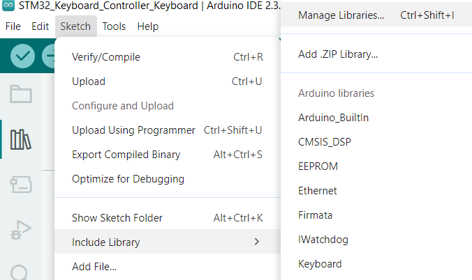
The last thing we need to do is install libraries. We will use two code libraries for our keyboard script to send keystrokes to the computer and read which keys were pressed. These are the Keyboard and Keypad libraries. To install the keypad library, go to Sketch > Include Library > Manage Libraries then search for “keypad” and click the install button for the first option.

The Keyboard library should already be included in your Arduino IDE install but if it turns out you don’t have it, you can get it the same way you did for the Keypad library above.
Code
For our 3X4 keyboard, there are two slightly different methods we can use, one that will work with the matrix diodes facing the rows, and one that will work with the matrix diodes facing the columns. The keypad library was designed for keypads with diodes facing the columns, but if you are using our Customizable Size Keyboard PCB the diodes are facing the rows so we came up with a workaround. The matrix diodes facing the rows method is below (which we will use for our keyboard build), and the matrix diodes facing the columns method can be found further down, here.
#include <Keypad.h>
#include <Keyboard.h>

const byte ROWS = 4; // put how many rows you have here
const byte COLS = 3; // put how many columns you have here

// this defines how we will reference to each key on the keyboard, not what each key does
// it will be our matrix
char keys[COLS][ROWS] = {
  {'a','d','g','j'},
  {'b','e','h','k'},
  {'c','f','i','l'}
};

byte rowPins[ROWS] = {PA2, PA3, PA6, PB1};
byte colPins[COLS] = {PB11, PB14, PA9};

Keypad keyboard = Keypad( makeKeymap(keys), colPins, rowPins, COLS, ROWS );

void setup() {
  Keyboard.begin();
}

void loop() {

    char key = keyboard.getKey();
    switch (key) {

        // make sure the character after each "case" is the same as in the above matrix
        case 'a':
            Keyboard.press('1');
            delay(100);
            Keyboard.releaseAll();
            break;
        case 'b':
            Keyboard.press('2');
            delay(100);
            Keyboard.releaseAll();
            break;
        case 'c':
            Keyboard.press('3');
            delay(100);
            Keyboard.releaseAll();
            break;
        case 'd':
            Keyboard.press('4');
            delay(100);
            Keyboard.releaseAll();
            break;
        case 'e':
            Keyboard.press('5');
            delay(100);
            Keyboard.releaseAll();
            break;
        case 'f':
            Keyboard.press('6');
            delay(100);
            Keyboard.releaseAll();
            break;
        case 'g':
            Keyboard.press('7');
            delay(100);
            Keyboard.releaseAll();
            break;
        case 'h':
            Keyboard.press('8');
            delay(100);
            Keyboard.releaseAll();
            break;
        case 'i':
            Keyboard.press('9');
            delay(100);
            Keyboard.releaseAll();
            break;
        case 'j':
            Keyboard.press('0');
            delay(100);
            Keyboard.releaseAll();
            break;
        case 'k':
            Keyboard.press(KEY_LEFT_CTRL);
            Keyboard.press('c');
            delay(100);
            Keyboard.releaseAll();
            break;
        case 'l':
            Keyboard.press(KEY_LEFT_CTRL);
            Keyboard.press('v');
            delay(100);
            Keyboard.releaseAll();
            break;
    }
}
Now lets break up this code to understand it.
char keys[COLS][ROWS] = {
  {'a','d','g','j'},
  {'b','e','h','k'},
  {'c','f','i','l'}
};
This is the matrix definition for the keyboard. You can see that it looks like 3 rows and 4 columns instead of the 4 rows and 3 columns our keyboard has. This is our work around to get by the matrix diodes that the keypad library expect to be facing the columns. It is essentially flipping the rows and columns to change which way the diodes face. Notice how the letters start by going down instead of to the right, like what a, b, and c are doing. This is a must for our work around because it will correctly line up the keys in firmware with the placement of the physical keys on our keyboard.
If you had a 4X5 (4 columns, 5 rows) keyboard, It would look like this:
char keys[COLS][ROWS] = {
  {'a','e','i','m','q'},
  {'b','f','j','n','r'},
  {'c','g','k','o','s'},
  {'d','h','l','p','t'}
};
You also need to know that the letters shown on that matrix are only for the firmware to look for them later when checking which keys were pressed. They do not define which keystroke will be sent to the computer, we will do that later in the code. You can use the ABCs for the matrix unless you run out of letters, which then you can use other single characters like numbers and symbols.
byte rowPins[ROWS] = {PA2, PA3, PA6, PB1};
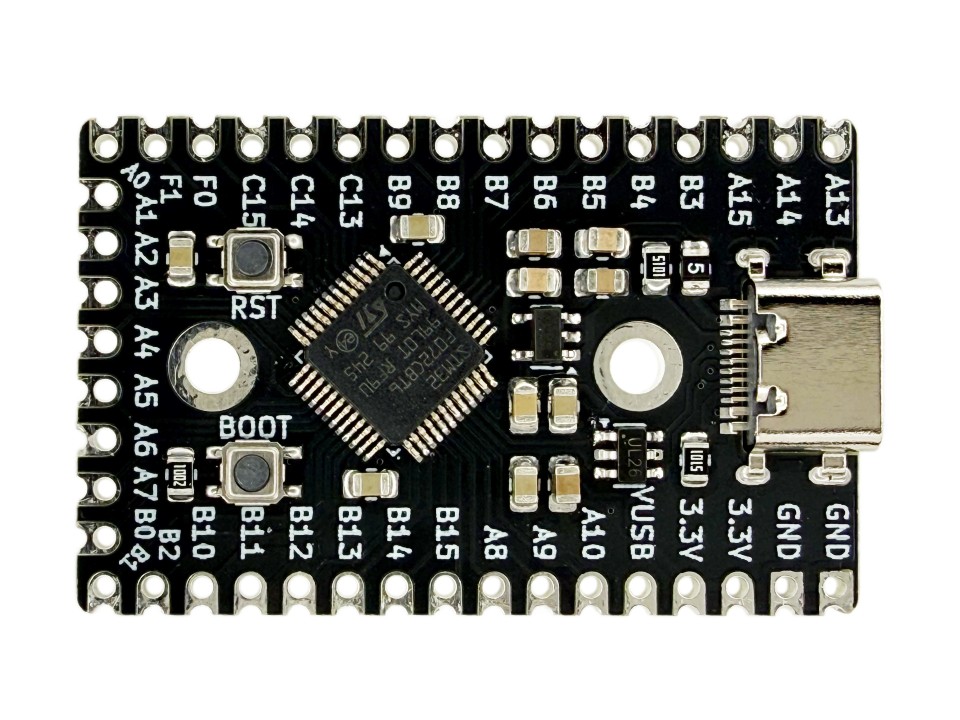
byte colPins[COLS] = {PB11, PB14, PA9};These lines define which pins the rows and columns are connected to. We connected our rows to pins A2, A3, A6, and B1 on our STM32 Keyboard Controller, and the columns to pins B11, B14, and A9. These are how the pins are labelled on the STM32 Keyboard Controller, but in the Arduino IDE we need to add the letter “P” in front of each pin name. (For example, PA2 instead of A2. This is how the pins are defined in STM32 Core.)
Keypad keyboard = Keypad( makeKeymap(keys), colPins, rowPins, COLS, ROWS );This line is just used to create an object, in our case named keyboard. It will use the data we gave it earlier in the code: colPins, rowPins, COLS, and ROWS.
Next, Keyboard.begin(); inside void setup() starts emulating a keyboard for the connected device. This only needs to be called once.
char key = keyboard.getKey();
switch (key) {

    case 'a':
        Keyboard.press('1');
        delay(100);
        Keyboard.releaseAll();
        break;
    ...
In void loop() we have a switch case. The code in a case will run if the variable “key” is the same as the character defined for the case. In the snippet above, if the variable “key” equals “a”, then this code will run:
Keyboard.press('1'); delay(100);Keyboard.releaseAll();
The variable “key” gets it’s value from the matrix we made earlier in the code, if the physical key for “a” is pressed, case “a” will run, if the physical key for “b” is pressed, case “b” will run, and so on.
In each case is where you will define which keystrokes are sent when a physical key is pressed. If the first key on our keyboard is pressed, we want to send the keystroke for “1” to the computer. We do this by using the Keyboard.press(); function, with the keycode for “1” (which is just “1”). Then we have a short delay and release the key so our keyboard does not keep it in the “pressed” state.
case 'k':
    Keyboard.press(KEY_LEFT_CTRL);
    Keyboard.press('c');
    delay(100);
    Keyboard.releaseAll();
    break;
Here is another case where we perform a copy shortcut. We use the Keyboard.press(); function to press the left ctrl key, and then use it again to press the “c” key. Then a short delay and a Keyboard.releaseAll(); function to stop pressing those keys. If you are having trouble finding the right keycode you want to use, you can find a full list here.
There are also other keyboard functions you can use to send keystrokes including Keyboard.print(); which sends a character or a string of characters. You can use it like this: Keyboard.print("Hello"); You can find other keyboard functions here.
Remember that you need as many cases as you have keys on your keyboard, and that they define each character used in the matrix definition.
Code for matrix diodes facing columns
#include <Keypad.h>
#include <Keyboard.h>

const byte ROWS = 4; // put how many rows you have here
const byte COLS = 3; // put how many columns you have here

// this defines how we will reference to each key on the keyboard, not what each key does
// it will be our matrix
char keys[ROWS][COLS] = {
  {'a','b','c'},
  {'d','e','f'},
  {'g','h','i'},
  {'j','k','l'}
};

byte rowPins[ROWS] = {PA2, PA3, PA6, PB1};
byte colPins[COLS] = {PB11, PB14, PA9};

Keypad keyboard = Keypad( makeKeymap(keys), colPins, rowPins, COLS, ROWS );

void setup() {
  Keyboard.begin();
}

void loop() {

    char key = keyboard.getKey();
    switch (key) {

        // make sure the character after each "case" is the same as in the above matrix
        case 'a':
            Keyboard.press('1');
            delay(100);
            Keyboard.releaseAll();
            break;
        case 'b':
            Keyboard.press('2');
            delay(100);
            Keyboard.releaseAll();
            break;
        case 'c':
            Keyboard.press('3');
            delay(100);
            Keyboard.releaseAll();
            break;
        case 'd':
            Keyboard.press('4');
            delay(100);
            Keyboard.releaseAll();
            break;
        case 'e':
            Keyboard.press('5');
            delay(100);
            Keyboard.releaseAll();
            break;
        case 'f':
            Keyboard.press('6');
            delay(100);
            Keyboard.releaseAll();
            break;
        case 'g':
            Keyboard.press('7');
            delay(100);
            Keyboard.releaseAll();
            break;
        case 'h':
            Keyboard.press('8');
            delay(100);
            Keyboard.releaseAll();
            break;
        case 'i':
            Keyboard.press('9');
            delay(100);
            Keyboard.releaseAll();
            break;
        case 'j':
            Keyboard.press('0');
            delay(100);
            Keyboard.releaseAll();
            break;
        case 'k':
            Keyboard.press(KEY_LEFT_CTRL);
            Keyboard.press('c');
            delay(100);
            Keyboard.releaseAll();
            break;
        case 'l':
            Keyboard.press(KEY_LEFT_CTRL);
            Keyboard.press('v');
            delay(100);
            Keyboard.releaseAll();
            break;
    }
}
This code is the same as the script for the keyboard with matrix diodes facing rows, but there is one difference in the matrix definition.
char keys[ROWS][COLS] = {
  {'a','b','c'},
  {'d','e','f'},
  {'g','h','i'},
  {'j','k','l'}
};
The matrix definition here will look the same as your keyboard looks, with the same rows and columns. “a” will be the first key on your keyboard, “b” will be the second, and so on.
If you had a 4X5 (4 columns, 5 rows) keyboard, It would look like this:
char keys[COLS][ROWS] = {
  {'a','b','c','d'},
  {'e','f','g','h'},
  {'i','j','k','l'},
  {'m','n','o','p'},
  {'q','r','s','t'}
};
Uploading to the Controller
Once you have finished configuring which keys your keyboard will have, it is time to upload the code to it. Find a USB-C cable (it can be any USB cable with a USB-C end) and plug one end into your computer. Make sure the board settings are still the same from what we set up at the start of this tutorial. Now hold down the BOOT button on your STM32 Keyboard Controller and then plug the cable into it. Leave the button pressed and everything as is, and press upload on the Arduino IDE. It should compile and upload successfully. After this, unplug and plug back in your cable to take the board out of bootloader mode so you can use your new keyboard!
If you get an error like this: STM32_Programmer.sh/STM32_Programmer_CLI.exe not found. make sure STM32CubeProgrammer is installed, and if it is, uninstall it and install it again, making sure to set it up with the default settings and file locations. More information can be found here.
This is the end of the tutorial. if you have any questions or feedback, please leave them in the comments below.


Leave a Reply