
Introduction
Our Tineato 3226 development board is great for projects that just need a simple and small microcontroller. But don’t get fooled by its size and price. The Tineato 3226 uses the latest and greatest from the ATtiny 2-series, the ATtiny3226! This microcontroller is as powerful (and in most cases even more) as the ATmega328P on an Arduino UNO. And compared to it’s predecessors like the ATtiny85, it has 4 times the flash memory and 6 times the SRAM. So if you need a simple but powerful ATtiny microcontroller, this is the board for you!
Features
The board itself includes a 5V or 3.3V regulator (depending on which board you have) that can be used to power itself with a power supply up to 24V and output up to 500mA on the VCC pin. There are 10 analog pins and 6 digital pins, 6 of which are PWM capable. The board has an FTDI style serial header and an auto-reset circuit for easy uploading. There is a red power indicator LED and an LED_BUILTIN LED connected to pin 3. And of course, the ATtiny3226’s features include:
- 32KB of flash memory
- 3072B of SRAM
- 256B of EEPROM
- Optiboot bootloader
- 12 bit ADC, 15 channels
- 20MHz for 5V version, 10MHz for 3.3V version
- 4.2V B.O.D. for 5V version, 2.6V B.O.D. for 3.3V version
Layout and Pinout
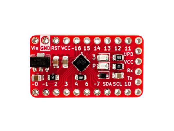
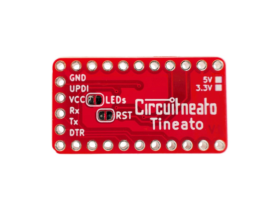
The first 4 pins at the top left are for power and reset, the rest of the pins around the edge of the board (besides the right edge) are GPIO pins, and the row of 6 pins on the right edge is the FTDI style serial header. The LED_BUILTIN LED is marked with a “3” on the silkscreen and the power LED is marked with a “P”. The back of the board has a jumper labeled “LEDs” which can be cut to disable all of the LED’s onboard. There is also another jumper labeled “RST” which can be cut to disable the auto-reset capacitor (more info at the end).

Below is a simplified diagram of the Tineato 3226.
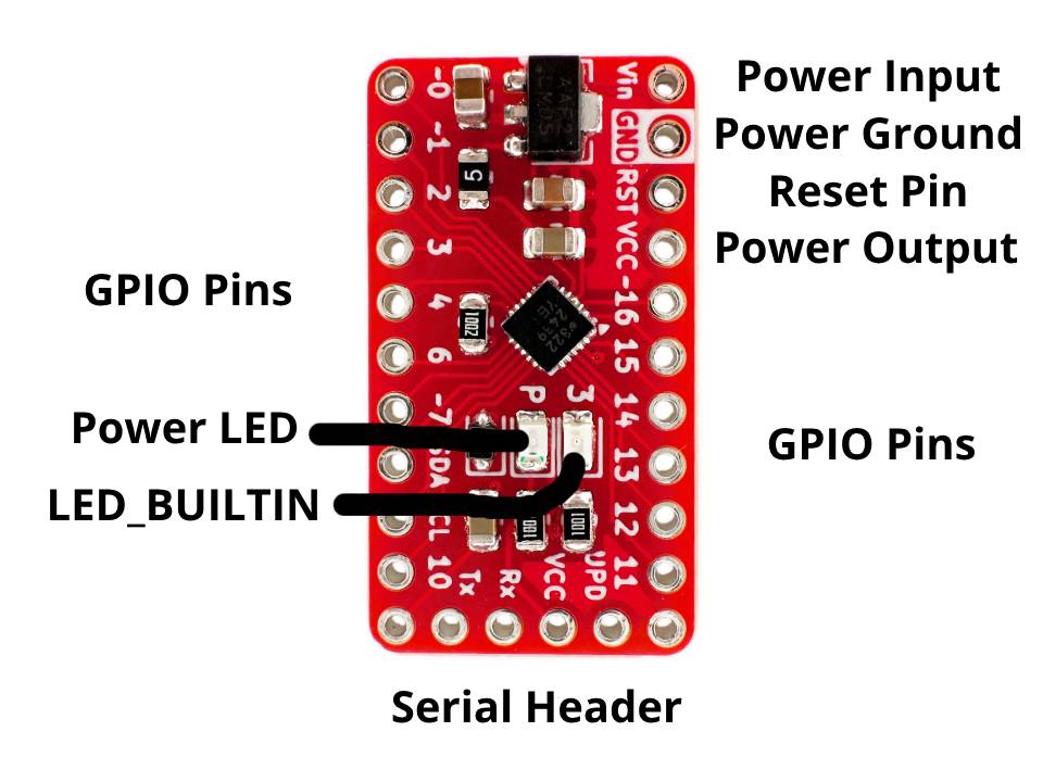
- Power Input Is for an external power source like a battery or a power supply. You can connect up to 24V to this pin, which will then be regulated down to 5V or 3.3V depending on which version you have. If you already have a regulated 5V or 3.3V power supply, you can connect that directly to the
VCCpin. The regulator also has over-current and over-temperature protection, and can output up to 500mA on theVCCpin. - Power Ground Is the common ground connection between everything on the board. If you are powering the board or connecting a device to it, you will likely need to connect this pin.
- Reset Pin Is for resetting the ATtiny3226. You may use this to restart the program running on the microcontroller. To use, connect the
RSTpin to theGNDpin for a short time. You can also wire a button to these pins for resetting the board from somewhere else. - Power Output is connected to the 5V or 3.3V power on the whole board and can be used to power small devices like motors and LED’s. It is also the output from the voltage regulator. The
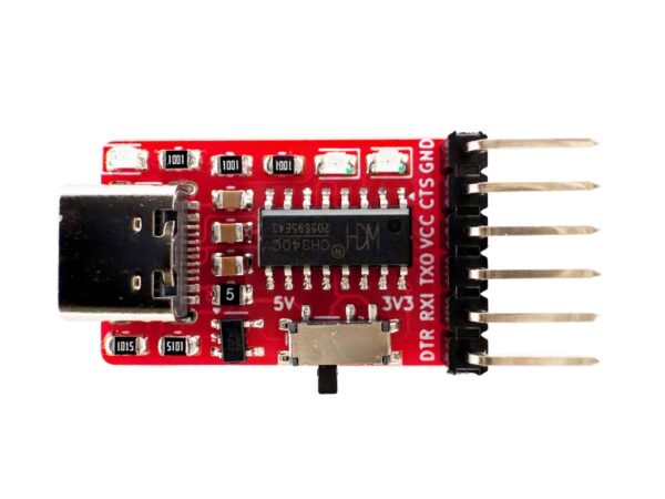
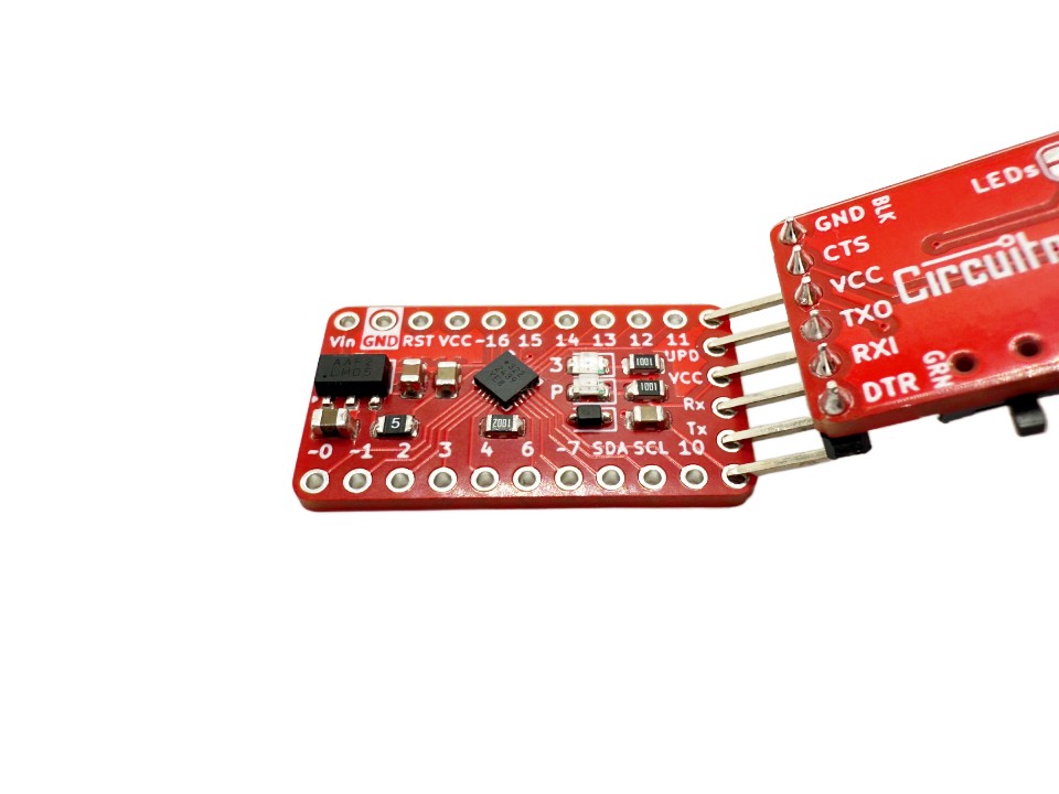
VCCpin can also be used as a power input ONLY if your supply is a regulated 5V or 3.3V (depending on which board you have) You can pull up to 500mA if powering through theVinpin or up to 1A if powering from the VCC pin directly. - Serial Header is for programming the board. Connect a serial adapter like this one to these pins, making sure that Tx on the board is connected to Rx of the serial adapter and vice-versa. If you are using a serial adapter like ours, you can simply stick the pins of the adapter into the board instead of connecting each pin individually with wires. The
UPDpin on the serial header is for UPDI programming and can be left unconnected. It may take the place of the CTS pin on your serial adapter which is fine. - Power LED lights up red if the board is connected to power, either through the
VCCpin or theVinpin. - LED_BUILTIN is an led that is connected to pin 3 on the board. You can write to it by calling it either “3” or “LED_BUILTIN” in the Arduino IDE. It can be helpful for debugging or for testing.
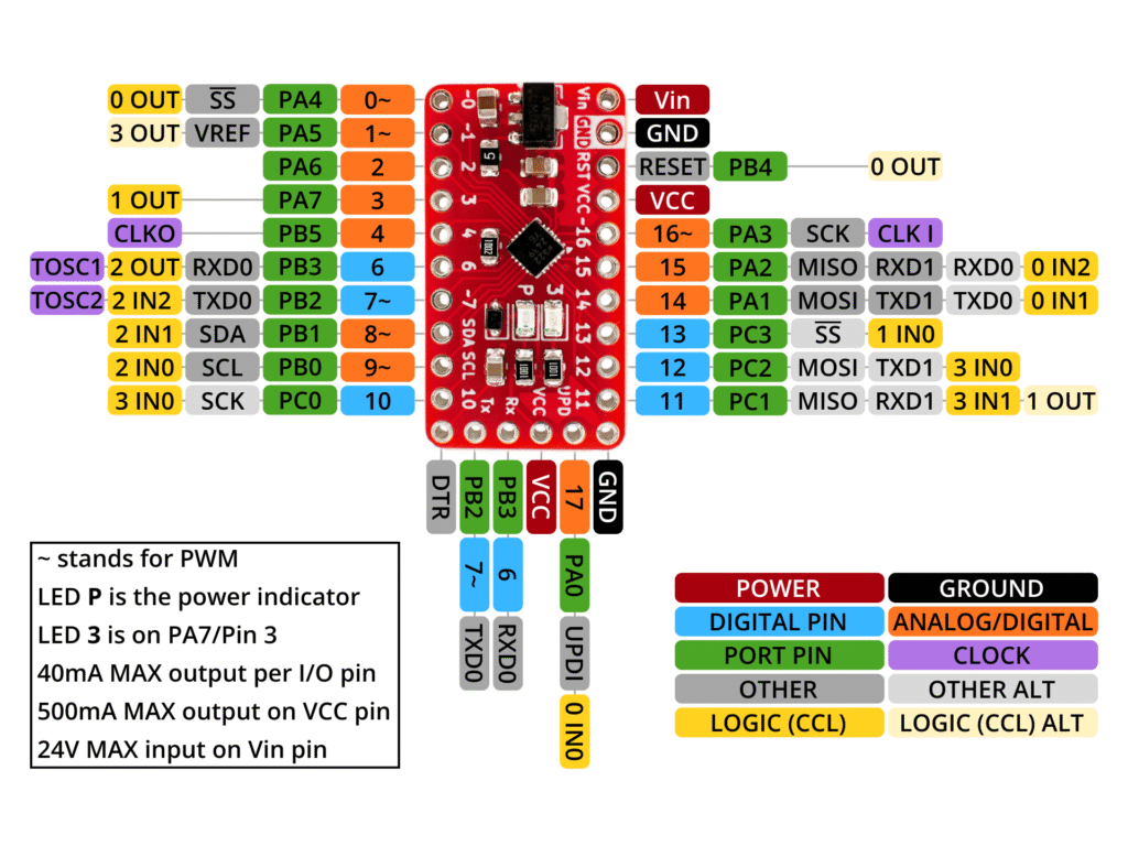
- GPIO Pins are the input and output pins on the board. There are 16 of them which can all be used as either inputs, or outputs. The pins labeled with an “~” are able to output a PWM signal. Some of these pins work as analog inputs which means you can input an analog signal into them that can then be read by the microcontroller. These pins are labeled in the pinout diagram below.
Here is the pinout diagram of the board. Key things to look out for are where the analog pins are, where the digital pins are, and where the PWM pins are.
Notes on GPIO Pins
Each GPIO pin can only supply up to 40mA, which means you can not run high power devices (like any motor) directly off of them. But for example, connecting an LED to a pin directly is okay. If you do want to control these high power devices, you can do so by using a transistor to supply the device with another power source like the VCC pin.
The GPIO pin marked “SDA” is pin 8 and has PWM support, and the GPIO pin marked “SCL” is pin 9 and also has PWM support.
If you have the 3.3V board, the GPIO pins will not tolerate 5V. On the other hand with the 5V board, it is safe to connect 3.3V to it’s GPIO pins, but it may not be okay to connect them to a 3.3V device. In either of these cases, you can use a level shifter like this one to convert the 5V signals to 3.3V or vise-versa.
Setup For Arduino IDE
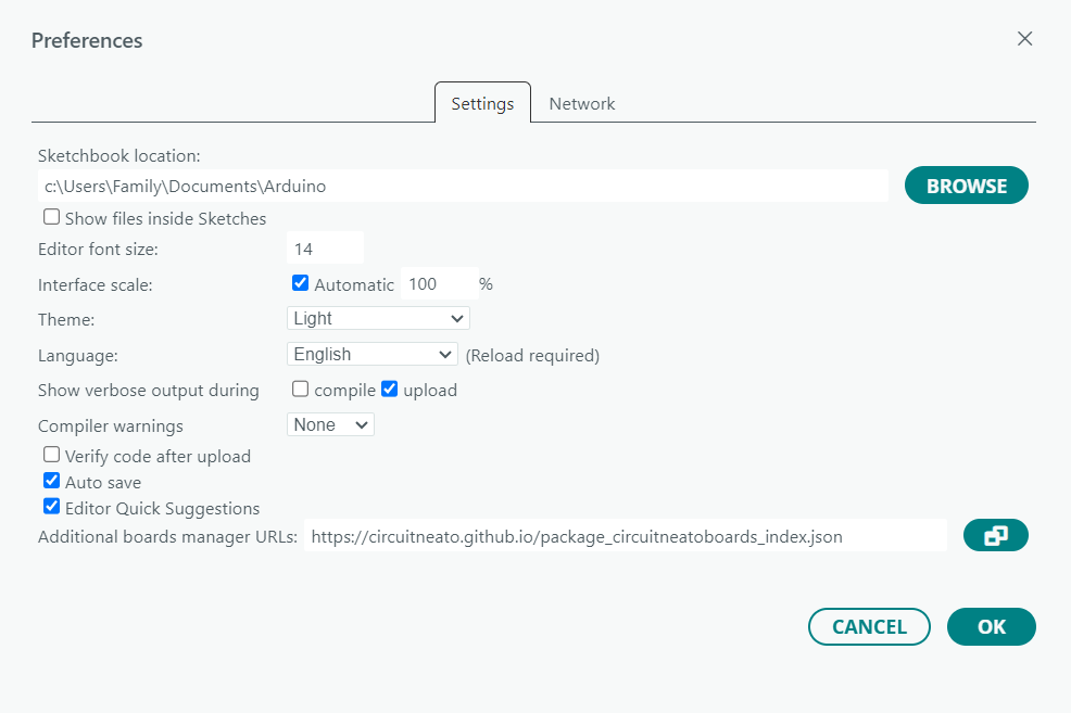
To program the Tineato 3226 with the Arduino IDE, we will just need to install a boards package for it, and then select the correct settings.
To install the boards package, go to File > Preferences then next to “Additional boards manager URL’s” enter this: https://circuitneato.github.io/package_circuitneatoboards_index.json (making sure it is on a new line if necessary).
Then go to the boards manager from Tools > Board > Boards Manager and search for “Circuitneato AVR Boards”. You should then click the Install button making sure it is the most recent version.
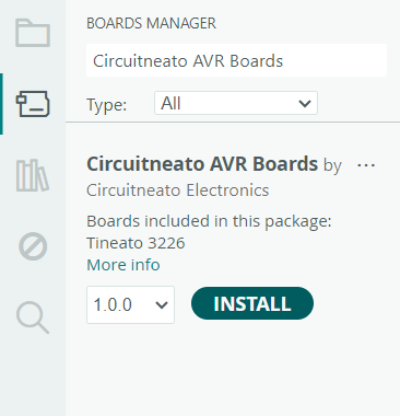
After it installs, go into Tools > Board > Circuitneato AVR Boards and select the Tineato 3226 option. Then in the tools menu again, you can select either Tineato 3226 5V/20MHz or Tineato 3226 3.3V/10MHz next to “Variant” depending on which board you have.

Programming With the Arduino IDE
You can write code for the Tineato 3226 like you would for any other Arduino board. For example, you can use digitalWrite(); and digitalRead(); to write either a high or low signal to any of the pins, or read a high/low signal from them.
You can also use analogWrite(); and analogRead(); to output a PWM signal on the PWM capable pins, or read an analog signal on the analog pins.
pinMode(); can be used to set a pin as an output, input, or an input with it’s internal pull-up resistor enabled.
Let’s start off with a simple blink sketch that will turn the LED_BUILTIN LED on and off.
void setup() {
  pinMode(LED_BUILTIN, OUTPUT);    // set the built-in led as an output
}

void loop() {
  digitalWrite(LED_BUILTIN, HIGH); // turn the LED on
  delay(1000);
  digitalWrite(LED_BUILTIN, LOW);  // turn the LED off
  delay(1000);
}
Uploading
To upload this code to the Tineato 3226, Push the pins on your serial adapter into the serial header’s pads on the board, and apply pressure to the adapter to ensure that all of the pins are connected. Make sure GND is connected to GND, VCC is connected to VCC (5V or 3.3V depending on your board), Rx is connected to Tx, Tx is connected to Rx, and DTR is connected to DTR. The UPD pin on the Tineato’s serial header does not need to be connected.
Use a USB cable to connect the serial adapter to your computer, and press upload in the IDE. Your code should successfully upload to the Tineato, and the built in LED should start blinking. If you got an error, make sure your board settings are correct, and double check your serial adapter’s connections to the board.

More Info
Jumpers
The LEDs jumper on the back of the board can be cut to disable both of the LEDs on the front of the board. You may do this if you don’t want pin 3 (the pin with the LED_BUILTIN LED on it) to be constantly pulled down by the LED’s resistor, or just don’t need the extra light.
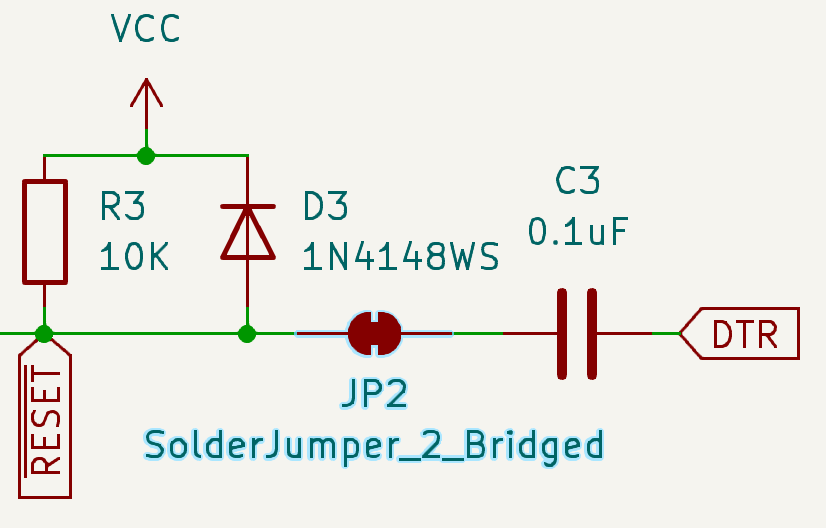
The RST jumper can be cut to disable the auto-reset capacitor. You may do this if you don’t want the board to automatically reset when using a serial adapter. Here is a snippet from the schematic of what this jumper does:


Leave a Reply
You must be logged in to post a comment.